FM15_P28 HV PN7 (-TS) Ver I_052217
Wire sizing data is provided in the table
to assist in the selection of the proper
wire size for ProMation actuators using
various wire sizes over distance.
Please make sure to reference the
correct voltage and do not exceed the
indicated length of the wire run for each
model.
Page 5 P2/3 HV-PN7 Series
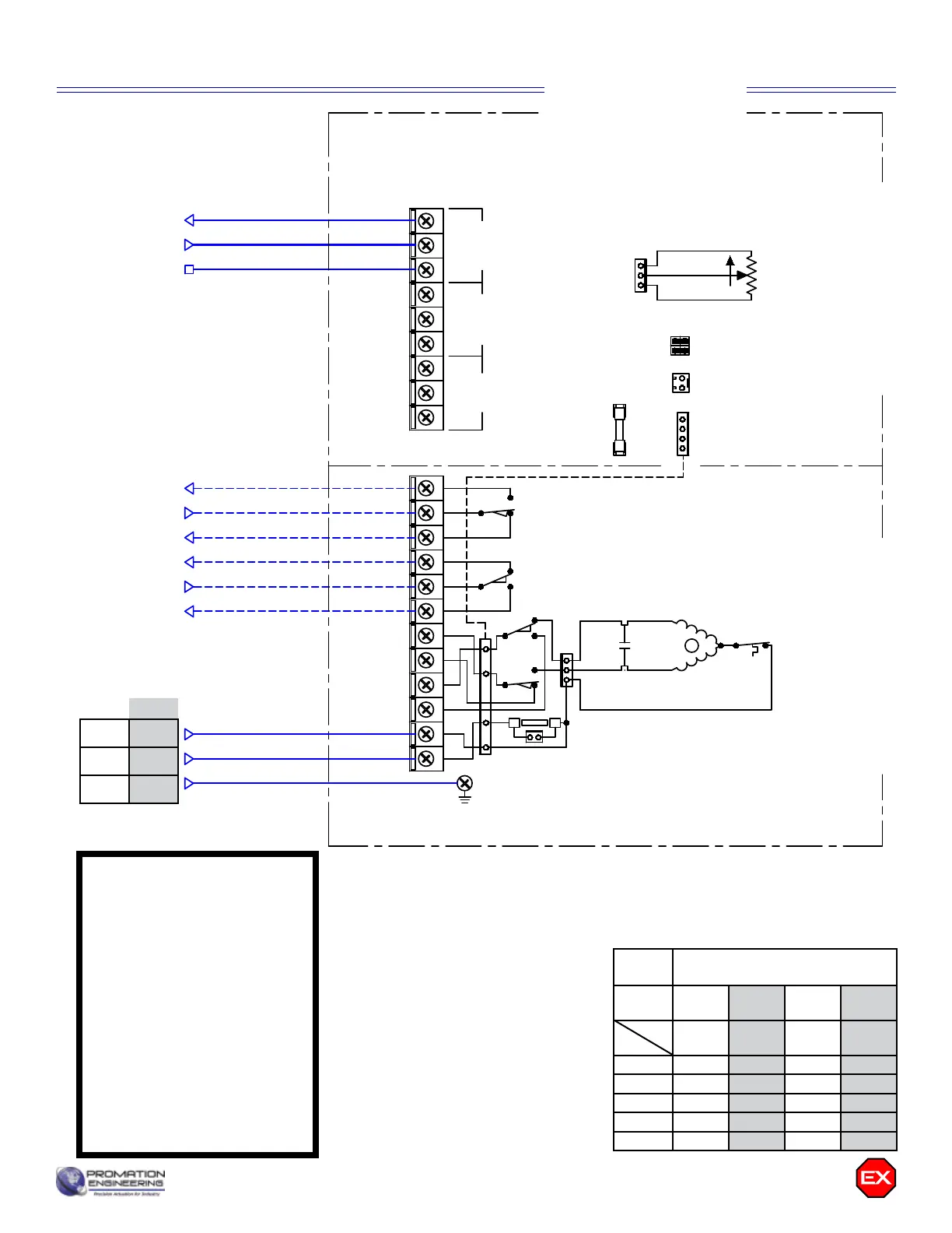
FEEDBACK OUT
SIGNAL IN
COMMON
OUT
IN
COM
COM
DIR
PWR
NC
NO
COM
ALARM PWR FAIL ANALOG
NOT OPEN*
OPEN COM*
OPEN*
NOT CLOSED*
CLOSED COM*
CLOSED*
NEUTRAL
HOT
12
11
10
9
8
7
120VAC
LINE IN
M
SW3
SW4
THERMAL
SWITCH
AC DRIVE
MOTOR
AUXILIARY
SWITCH
(STANDARD)
ALL SWITCHES
SHOWN WITH
ACTUATOR IN
FULL OPEN
POSITION
AUXILIARY
SWITCH
(STANDARD)
* CONNECTIONS
OPTIONAL
GND Screw
GND
Close
POSITION
FEEDBACK
1K ohm
J5
J4
FACTORY
CONNECTOR
6.3A
250V
3AG
SLO
F4
410-20112
Items within dotted line indicates internal components
6
5
4
3
2
1
J1
HEATER
SW1
SW2
J2
E1E2
J3
1
1 2 43
430-10102 Controller430-10100 Switch Card
1
BLU
ORG
GRY
BLK
RED
WHT
BLK
WHT
Capacitor
410-30110
25uF/250V
P2/3-120PN4
D
Actuator ships in fully closed position!
Use For:
WD-850-24201
120VAC
SELECT
J2
1
2 4
3
OPTION
POWER
J3
Wiring Diagram for P2~3 Series
Capacitor
Motor
Field Wiring (By Others)
Proportional Control
120VAC 230VAC
Neu L2
Hot L1
GND GND
Actuator Speci cations
P2 P3
Torque “lb/Nm 800”lbs/90Nm 1335”lbs/150Nm
Supply Voltage 120vac 230vac 120vac 230vac
Max Inrush Current 1.8A 0.8A 1.8A 1.2A
Running Current 1.0A 0.5A 1.2A 1.0A
Motor Split Phase Capacitor
Runtime (90°@60Hz) 15 sec 22 sec
Runtime (90
O
@50Hz) 17 sec 26 sec
Duty Cycle Managed (75% maximum)
Motor Starts 1200 per hour
Weight 36lbs/16kg
Mechanical Connections ISO5211 F07 8pt 22mm
Electrical Entry (2) 3/4” NPT
Electrical Terminations 12-16ga
Environmental Rating Class I Division 1, Class II Division 1
Manual Override 5” Handwheel
Control Proportional
Actuator Case material Aluminum Alloy, Powder coated
Motor Protection
230°F/110°C Thermal F* Class
*Totally Enclosed Non-Ventilated Motors
Ambient Temperature
Operating Range
-22°F to +125°F
-30°C to +52°C
P23 HV PN7
Wire Sizing Chart
MAX distance between Actuator
and Supply (feet)
Actuator/
Voltage
P2
120VAC
P2
230VAC
P3
120VAC
P3
230VAC
1.8A 0.8A 1.8A 1.2A
16 722 3111 722 2074
14 1166 5026 1166 3351
12 1783 7687 1783 5125
10 3030 13068 3030 8712
8 4523 19505 4523 13003
Wire
Gage
Amps
SINGLE PHASE ONLY
Potential between L1 and
L2 must be between 208
and 230VAC single phase
UNE SEULE PHASE
SEULEMENT
Le potentiel entre L1 et
L2 doit être compris entre
208 et 230 VAC en phase
unique