Menu Navigation
Page 7 of 102
2 Navigating the [Menu] display
Table 2 Main Menu lookup
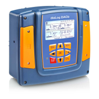
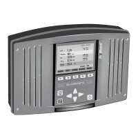
Figure 4 Typical default screen Figure 4A Screen if any alarm present
The default display exhibits up to six current sensor values, and STATUS, ALARM and SETPNT buttons. The sensor
choices can be changed or rearranged. See section 2.2 How to Modify the Display’s ‘Home’ Screen. The STATUS
button (F1) is explained in section 2.1 Input/Output Status. The Alarm button (F2) allows the user to view and clear the
latest alarms for all I/O points. See also section 9.8.1 Analog Alarm Configuration, for more information on alarms.
The SETPNT button (F3) allows the user to edit the set-point of any enabled relay using set-points.
ª Return to the default display (See below)
ª Chapter 10.6.2 Feed Based on a Sensor
ª Chapter 10.14 Prime, Force On a Relay
ª Chapter 9.10.1 Configure a Digital Input as a Water Meter
ª Chapter 9.8.1 Analog Alarm Configuration
ª Chapter 10.7 Configuring an Event-Other relay
ª Chapter 10.6 Configuring a Feed Relay
ª Chapter 10.5 Configure a Blowdown Relay
ª Chapter 9.1 Analog and Digital Inputs
ª Chapter 10 Programming the Control Outputs Use this menu
choice to monitor the I/O
 Loading...
