S
Sarah KennedyAug 3, 2025
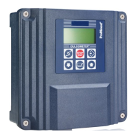
Why does my ProMinent DULCOMETER Compact Controller display 'pH/mV RANGE'?
- PPamela Joseph MDAug 3, 2025
The 'pH/mV RANGE' error on your ProMinent Controller can appear if the input voltage is either too low or too high, indicating a fault current.