15 Replacing spare part units
n User qualification, mechanical instal‐
lation: trained qualified personnel, see
Ä Chapter 3.4 ‘Users' qualifications’
on page 14
n User qualification, electrical installa‐
tion: Electrical technician, see
Ä Chapter 3.4 ‘Users' qualifications’
on page 14
CAUTION!
Check strap for strain relief
Possible consequence: Material
damage.
The ribbon cable and its base cannot
be mechanically stressed. Hence it is
essential when mounting the con‐
troller in the control panel, that the
check strap (part number 1035918) is
fitted for strain relief and mechanical
fixing. Without the check strap, the
ribbon cable or its base could be
damaged if they were to fall out of the
top part of the controller housing.
15.1 Replacing the top part of
the housing
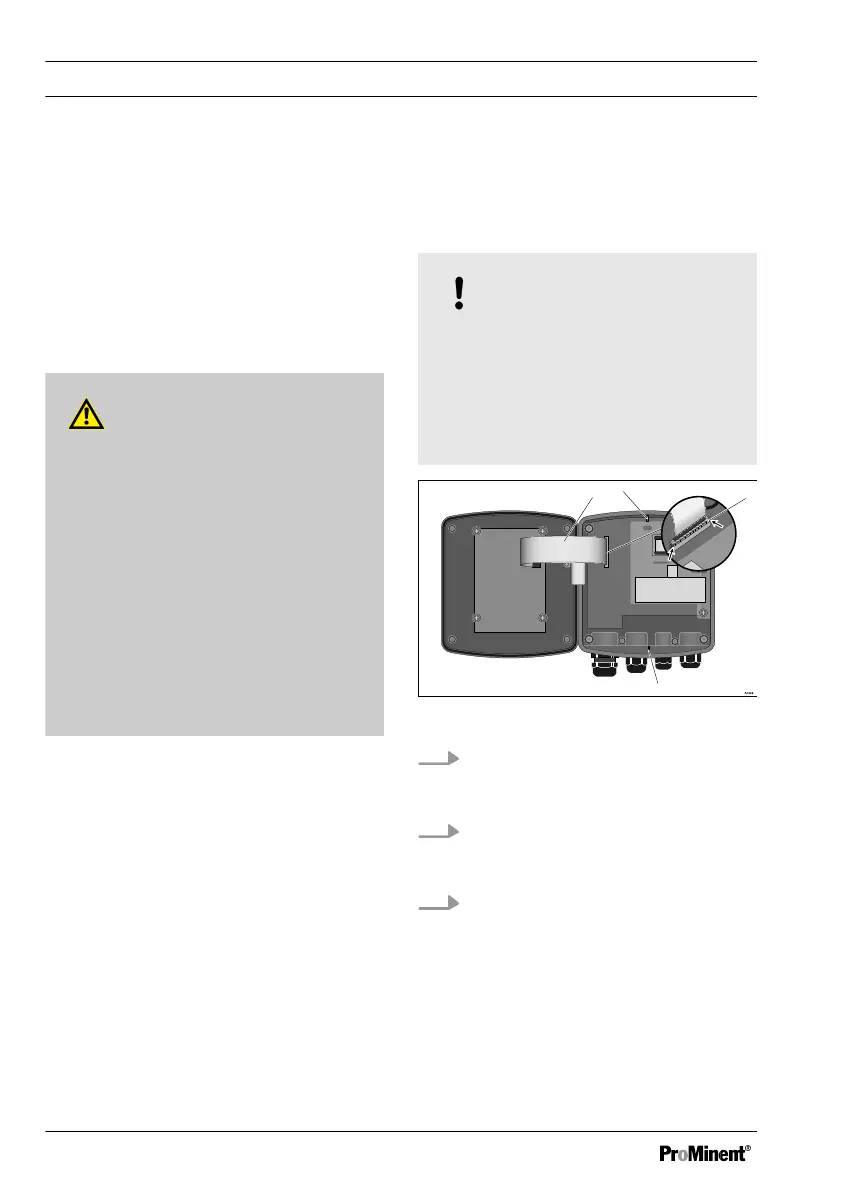
NOTICE!
Ribbon cable base
The base of the ribbon cable is firmly
soldered onto the PCB. The base
cannot be removed. Open the base
lock (3) to loosen the ribbon cable,
see Fig. 36
Fig. 36: Loosening the ribbon cable
1.
Undo four screws and open the
DULCOMETER
®
Compact Con‐
troller
2. Open the right and left lock (3)
(arrows) on the base and pull the
ribbon cable (1) out of the socket
3. The catches (2 and 4) are not
needed with units for control panel
installation.
Replacing spare part units
102