Do you have a question about the ProMinent DULCOMETER diaLog DACb and is the answer not in the manual?
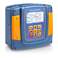
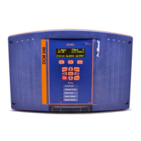
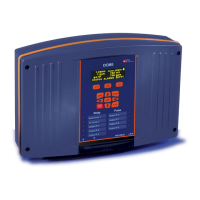
Identifies the DULCOMETER® Multi-parameter controller diaLog DACb.
Describes the controller's display and control keys.
Explains the different warning symbols and their meanings.
Warns about dangers from unqualified personnel and defines qualifications.
Details the process for saving the controller configuration as a text file to an SD card.
Specifies the required installation site conditions and environmental considerations.
Provides step-by-step instructions for wall mounting the controller.
Warns about electrical voltage on output relays and necessary precautions.
Explains how to connect a chlorine sensor in a two-channel configuration.
Recommends using pre-assembled coaxial cables for sensor connection.
Details the controller's behavior when first switched on during commissioning.
Explains that settings for Channel 1 apply to other channels with potential differences.
Notes that Channel 1 settings apply to other channels with potential differences.
Lists the valid zero point and slope values for pH sensor calibration.
Emphasizes correct sensor operation as a prerequisite for accurate calibration.
Outlines the two available calibration processes for the ORP sensor.
States that calibration procedures are the same for all amperometric variables.
Warns about correct sensor operation and run-in periods for slope calibration.
Guides on determining the appropriate calibration interval for sensors.
Details calibrating conductive conductivity and adjusting sensor parameters.
Explains that settings for Channel 1 apply to other channels with potential differences.
Explains that limit values are compared continuously with the measured value.
Details how to set Limit 1 for a measuring channel.
Details the setup process for Pump 1, which applies to other pumps.
Shows the main screen for configuring Relay 1 settings.
Shows the screen for configuring digital inputs.
Notes that mA output settings for channels 2 and 3 are similar to channel 1.
Discusses data backup, service life of SD cards, and responsibilities.
Details how to record, read, and clear entries in the calibration log book.
Guides on accessing calibration, error, and data log books.
Lists error codes, their causes, and remedies.
Lists measuring ranges for different connector types and variables.
Lists available spare parts and their order numbers.
Guides on replacing the upper housing part with the display.
Advises on regulations for the disposal of used parts and decontamination.
| Type | Controller |
|---|---|
| Operating Temperature | 0 to 50 °C |
| Input Signals | pH, Redox, Conductivity, Temperature |
| Enclosure Protection | IP65 |
| Measurement Range pH | 0 to 14 pH |
| Measurement Range Redox | -2000 to +2000 mV |
| Display | Graphic display |
| Input Voltage | 100-240 V AC |
| Output Signals | 4-20 mA |
| Control Functions | PID control |
| Power Supply | 100-240 V AC |
| Measurement Range Conductivity | 0 to 200 mS/cm |
| Inputs | pH, Redox, Conductivity, Temperature |




 Loading...