9 Configuring measured variables
n User qualification: trained user
Ä Chapter 3.4 ‘User qualification’ on page 24
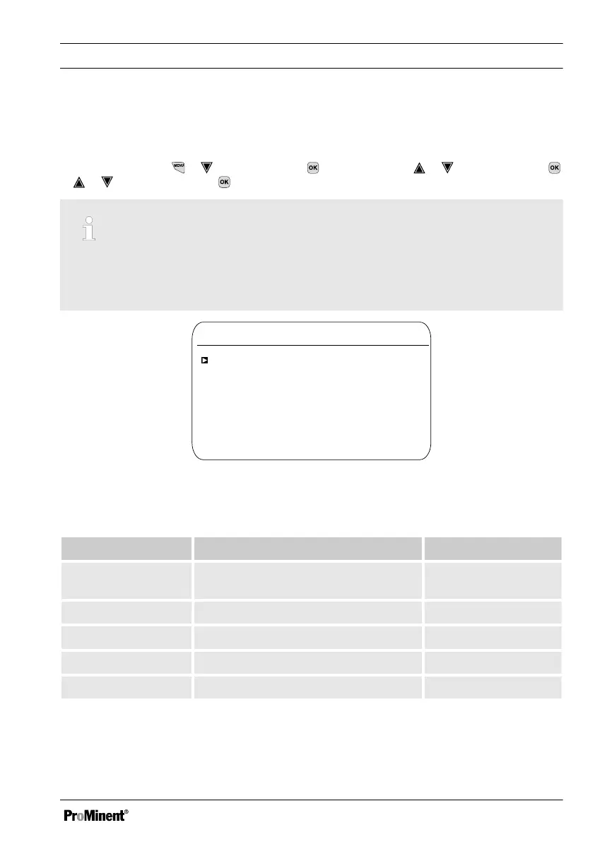
Continuous display ➨ ➨
[Measurement]
➨
[Measurement]
➨ or
[Meas. channel 1]
➨ or
[Measured variable]
.
Measuring channel settings
This descriptions of [Channel 1] apply correspondingly to the settings in all other measuring
channels. The procedure for entering the settings for the channel in question is identical,
however the parameters to be set may differ. Your attention is drawn to the differences,
which are also described.
Channel 1
Measured variable
A1082
Chlorine
Sensor type
Measuring range
Temperature
Process temperature
pH compensation
CLE3/CLE3.1
0... 2.0 ppm
Manual
10.0 °C
Off
Fig. 31: Setting measured variables, using the example of [Channel 1] and [Chlorine].
Tab. 10: The following measured variables can be set at the controller:
Measured variable Meaning Unit
[None]
The controller does not carry out any meas‐
urement.
[pH [mV]]
pH sensor with mV signal
[pH]
[pH [mA]]
pH sensor with mA signal
[pH]
[ORP [mV]]
ORP sensor with mV signal
[mV]
[ORP [mA]]
ORP sensor with mA signal
[mV]
Configuring measured variables
69