Do you have a question about the ProMinent DULCOMETER D1Cb and is the answer not in the manual?
Details about safety symbols and categories used in the manual.
Defines the required training and qualifications for personnel operating the device.
Provides essential safety warnings regarding live parts and unauthorized access.
Specifies the intended use and limitations of the device.
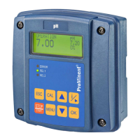
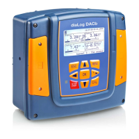
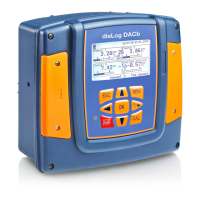
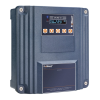
Describes the housing and mounting options for the D1Cb controller.
Details the device's electrical setup and operational readiness.
Step-by-step guide for installing the device on a wall.
Instructions for installing the device into a control panel.
Guide for connecting the device electrically when wall-mounted.
Details on RC circuits to protect relay contacts from inductive loads.
Specifies required qualifications for mechanical and electrical mounting.
Instructions for installing the D1Cc device into a control panel.
Guide for electrical connections when the device is panel-mounted.
Specifies that a trained user is required for commissioning the device.
Highlights the importance of sensor run-in times for accurate measurements.
Procedure for selecting the correct measurement variable and range.
Details how the device displays and handles error messages.
Specifies user requirements for operating amperometric sensor functions.
Procedure for calibrating amperometric sensors.
Instructions for calibrating the sensor's zero point and slope.
Detailed steps for calibrating the slope of amperometric sensors.
Procedure for calibrating the zero point of amperometric sensors.
Guide for matching the device to third-party sensors.
General guidelines and warnings for calibrating these sensor types.
Detailed explanation and procedure for calibrating pH sensors.
Step-by-step guide for performing a two-point calibration on pH sensors.
Details error messages and their effects during pH sensor calibration.
Procedure for testing redox sensors, not calibrating them.
Explains the process and expected outcomes of redox sensor testing.
Details error messages and their effects during redox sensor testing.
Explanation and procedure for calibrating fluoride sensors.
Step-by-step guide for a two-point calibration of fluoride sensors.
Information on one-point or two-point calibration options for standard signals.
Procedure for selecting and changing the measured variable.
Explains the two operating modes for parameter access.
Guide for adjusting the device's reading and range.
Procedure for calibrating the standard signal (zero point and two-point).
Steps for performing a zero point calibration on the standard signal.
Steps for performing a two-point calibration on the standard signal.
Access to various sub-functions for device configuration.
Procedure to select and set the required measuring variable and range.
Option to change the measured variable based on enabling codes.
Table listing error messages, their causes, and effects.
| Type | Controller |
|---|---|
| Measurement Range pH | 0 - 14 pH |
| Measurement Range Conductivity | 0 - 200 mS/cm |
| Input Signals | Analog, Digital |
| Output Signal | 0/4 - 20 mA |
| Protection Class | IP65 |
| Display | LCD |
| Temperature Compensation | Automatic |
| Operating Temperature | 0 - 50 °C |
| Measured Variables | pH, Redox, Conductivity |
| Measurement Range (mg/L) | 0.01 - 20 mg/L |
| Output Signals | Analog |
| Communication | RS-485, Modbus |
| Power Supply | 100 - 240 V AC |



 Loading...