4.4 Switching of inductive loads
If you connect an inductive load, i.e. a
consumer which uses a coil (e.g. an
alpha motorised pump), then you
must protect your controller with a
protective circuit. If in doubt, consult
an electrical technician for advice.
The RC member protective circuit is a
simple, but nevertheless very effective,
circuit. This circuit is also referred to as a
snubber or Boucherot member. It is pri‐
marily used to protect switching contacts.
When switching off, the connection in
series of a resistor and capacitor means
that the current can fade out in a damped
oscillation.
Also when switching on, the resistor acts
as a current limiter for the capacitor
charging process. The RC member pro‐
tective circuit is highly suited to AC
voltage supplies.
The magnitude of the resistance R of
the RC member is determined according
to the following equation:
R=U/I
L
(U= Voltage divided by the load // I
L
=
load current)
The magnitude of the capacitor is deter‐
mined using the following equation:
Units: R = Ohm; U = Volt; I
L
= Ampere;
C = µF
C=k * I
L
k=0,1...2 (dependent on the application).
Only use capacitors of class X2.
Units: R = Ohm; U = Volt; I
L
= Ampere;
C = µF
If consumers are connected which
have a high starting current (e.g. plug-
in, switched mains power supplies),
then a means of limiting the starting
current must be provided.
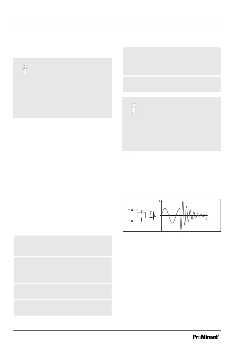
The switching-off process can be investi‐
gated and documented using an oscillo‐
scope. The voltage peak at the switch
contact depends on the selected RC com‐
bination.
Fig. 21: Switching-off process shown on
the oscillogram.
D1Cc mounting
50