At the end of the (Timer) cycle time, the DULCOMETER
®
D1Cb / D1Cc closes the corre‐
sponding timer relay for the duration of
"t on" (Timer). "Pause" interrupts the timer. If the
clock is visible on the LCD display, then the timer can be reset to the beginning of the
cycle using the enter key. The % specification on the LCD display indicates the remaining
runtime.
10.2.1.5 Setting and functional description of "Relay Used as a Solenoid
Valve"
Only with limit value relay or solenoid valve relay
relays
setting ?
solenoid valve 1
SV1↑
period 10 s
min. time
1
s
solenoid valve 2
SV2 ↓
period 10 s
min. time 1 s
relay adjustment
relay1: SV1
relay2: SV2
A0022_GB
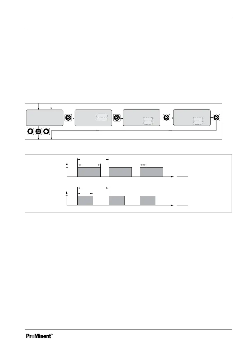
Fig. 61: Solenoid valve relay
Cycle
min. time
Solenoid
valve
off
on
t
t
on
off
on
t
t
on
Cycle
Actuating
variable: 50 %
t
on
Cycle
= 0.50
Actuating
variable: 80 %
t
on
Cycle
= 0.80
A0025_GB
Fig. 62: Solenoid valves
The switching times of the relay (solenoid valve) depend on the control value and on the
"minimum time" (smallest permissible switching time of the connected device). The con‐
trol value determines the ratio ton/cycle and thus also the switching times.
Operating Menus Independent of Measured Variables
119