1 Operating concept
1.1 Display and keys
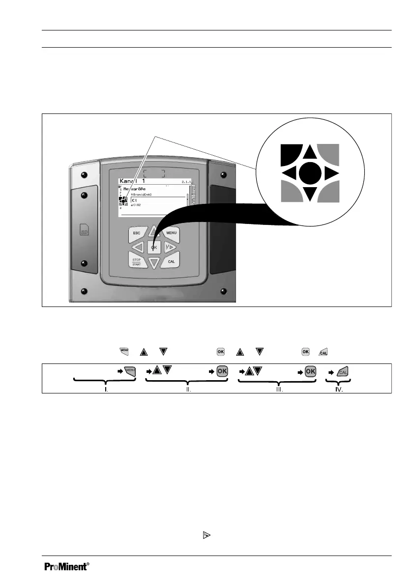
Fig. 1: Operating cross (1) / Active keys are displayed in [black] in the display; inactive keys in [grey].
The following path is shown as an example:
Continuous display ➨ ➨ or
[Calibrate]
➨ ➨ or
[Slope]
➨ ➨ .
Continuous display
[Calibrate] [Slope]
A1036
Fig. 2: A display change is made within a sequence of actions.
I. Continuous display 1
II. Display 2
III. Display 3
IV. Display 4
The function of the keys is described in the table
Ä Chapter 1.2 ‘Functions of the keys ’
on page 13
.
➨ = describes as a symbol an action by the operator that leads to a new possibility for an action.
[Naming in the display]
= square brackets contain the name that appears with the identical wording
in the controller display.
Additional information can be obtained via the key.
Operating concept
9