13 Setting the
[Pumps]
n User qualification: trained user, see
Ä Chapter 3.4 ‘User qualification’
on page 24
Continuous display ➨ ➨ or
[Pumps]
➨
[Pumps]
Measuring channel settings
This descriptions of [Channel 1] apply
correspondingly to the settings in all
other measuring channels. The proce‐
dure for entering the settings for the
channel in question is identical, how‐
ever the parameters to be set may
differ. Your attention is drawn to the dif‐
ferences, which are also described.
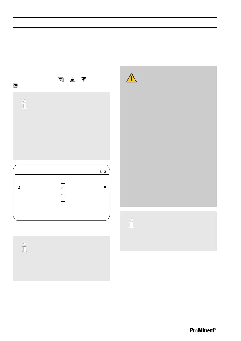
Pumps
A1064
Pump 1 channel 1
Pump 2 channel 1
Pump 3 channel 2
Pump 4 channel 2
Fig. 98: Setting the [Pumps]
Setting [Pump 1] or [Pump 2]
Only the process for[ Pump 1] is
described. The set-up process for
[Pump 2], [Pump 3] or [Pump 4] is the
same as for [Pump 1].
13.1 Setting [Pump 1]
CAUTION!
Refer to the operating manual for the
pump
Possibility of damaging the pump.
Faults in the process.
– Set the pump to
[External Contact]
operating status
– Observe the maximum stroke rate
for the pump
– Switch off any stored stroke set‐
tings in the pump control
– The maximum stroke rate for the
pump can be found in the pump
operating manual
– Setting a stroke rate on the
controller, which is higher
than the pump's actual pos‐
sible maximum stroke rate,
can lead to hazardous oper‐
ating statuses
Maximum pump frequency
The pumps are activated according to
the control variable up to the pump's
respective maximum stroke rate.
Setting the
[Pumps]
144