14. Push and lock the ribbon cable (1)
in its base. The catches (2 and 4)
are used to aligned the two halves
of the housing.
15. Screw the top part of the controller
housing onto the lower part of the
DULCOMETER
®
Compact Con‐
troller housing
16. Re-check that the seal is seated
properly. IP 67 degree of protection
(wall/pipe-mounting) can only be
provided if the installation is correct
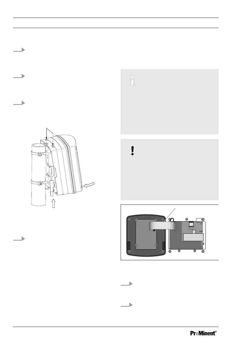
Fig. 45: Suspend and secure the
DULCOMETER
®
Compact Controller
17.
Suspend the DULCOMETER
®
Compact Controller at the top (1) in
the wall/tube retaining bracket and
push using light pressure at the
bottom (2) against the wall/pipe
retaining bracket. Then press
upwards (3) until the
DULCOMETER
®
Compact Con‐
troller audibly snaps into position
15.3 Replacing the lower part
of the housing (control
panel installation)
Complete commissioning of the
controller
Once the lower part of the housing
has been replaced, it is necessary to
fully commission the measuring and
control point, as the new lower part of
the housing does not have specific
settings, only factory settings.
NOTICE!
Ribbon cable base
The base of the ribbon cable is firmly
soldered onto the PCB. The base
cannot be removed. Open the base
lock (3) to loosen the ribbon cable,
see Fig. 36
Fig. 46: Loosen the ribbon cable from the
base
1. Undo four screws and open the
DULCOMETER
®
Compact Con‐
troller
2. Open the right and left lock on the
base and pull the ribbon cable (1)
out of the base.
Replacing spare part units
106