5.3.4 Installation (electrical)
The cable must be routed in a site-
provided cable duct to ensure strain
relief
1. Undo the four housing screws
2. Slightly lift the controller housing
top section forwards and fold it to
the left
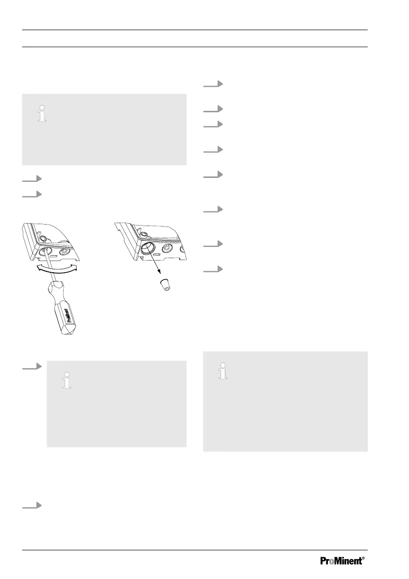
Fig. 14: Punch out threaded holes
3.
Large threaded connection (M
20 x 1.5)
Small threaded connection (M
16 x 1.5)
Punch out as many threaded con‐
nections on the bottom side of the
controller housing bottom section
as required
4. Guide the cable into the respective
reducing inserts.
5.
Insert the reducing inserts into the
threaded connectors
6. Guide the cable into the controller.
7. Connect the cable as indicated in
the terminal diagram
8. Screw the required threaded con‐
nections in and tighten
9. Tighten the clamping nuts of the
threaded connections so that they
are properly sealed
10. Click the controller housing top sec‐
tion on to the controller housing
bottom section
11. Manually tighten the housing
screws
12. Once again check the seating of the
seal. Only if the mounting is correct,
is protection class IP 67 (wall/pipe
mounting) or IP 54 (control panel
mounting) achieved
5.4 Switching of inductive loads
If you connect an inductive load, i.e. a
consumer which uses a coil (e.g. an
alpha motorised pump), then you
must protect your controller with a
protective circuit. If in doubt, consult
an electrical technician for advice.
The RC member protective circuit is a
simple, but nevertheless very effective,
circuit. This circuit is also referred to as a
snubber or Boucherot member. It is pri‐
marily used to protect switching contacts.
Assembly and installation
38