When switching off, the connection in
series of a resistor and capacitor means
that the current can be dissipated in a
damped oscillation.
Also when switching on, the resistor acts
as a current limiter for the capacitor
charging process. The RC member pro‐
tective circuit is highly suitable for AC
voltage supplies.
The magnitude of the resistance R of
the RC member is determined according
to the following equation:
R=U/I
L
(Where U= Voltage across the load and
I
L
= current through the load)
The magnitude of the capacitor is deter‐
mined using the following equation:
C=k * I
L
k=0,1...2 (dependent on the application).
Only use capacitors of class X2.
Units: R = Ohm; U = Volt; I
L
= Ampere;
C = µF
If consumers are connected which
have a high starting current (e.g. plug-
in, switched mains power supplies),
then a means of limiting the starting
current must be provided.
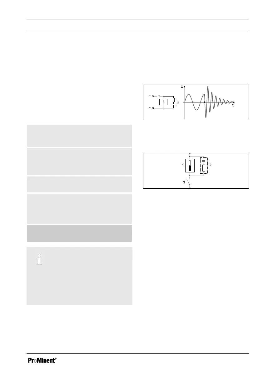
The switching-off process can be investi‐
gated and documented using an oscillo‐
scope. The voltage peak at the switch
contact depends on the selected RC com‐
bination.
Fig. 15: Switching-off process shown on
the oscillogram.
Fig. 16: RC protective circuit for the relay
contacts
Typical AC current application with an
inductive load:
n 1) Load (e.g. alpha motor-driven
pump)
n 2) RC-protective circuit
– Typical RC protective circuit at
230 V AC:
– Capacitor
[0.22µF/X2]
– Resistance
[100 Ohm / 1 W]
(metal oxide (pulse resistant))
n 3) Relay contact (XR1, XR2, XR3)
Assembly and installation
39