Now you must first activate the analog outputs:
–
Analog output 2 [Iout2] for circulation 1 (UW1)
–
Analog output 4 [Iout4] for circulation 2 (UW1)
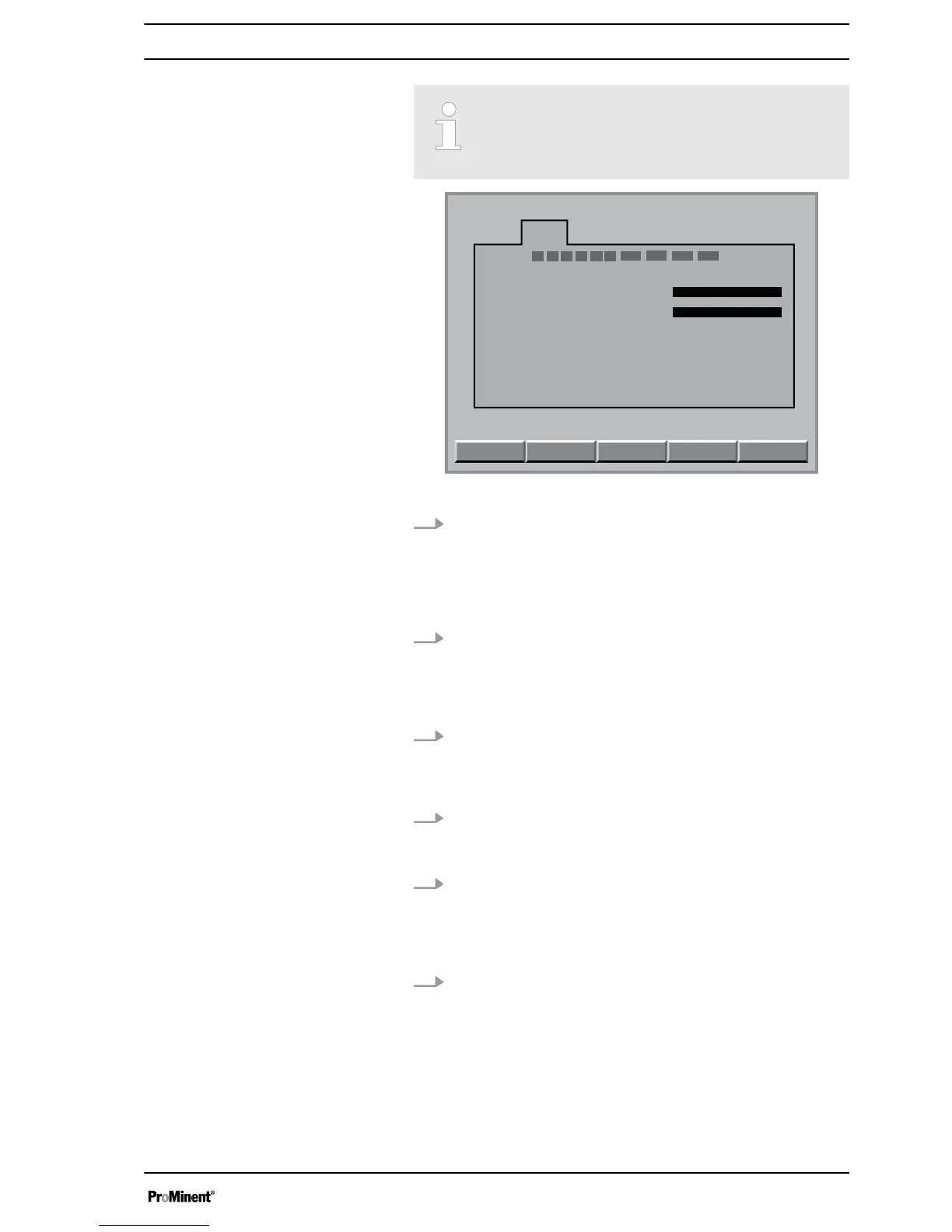
Fig. 3: Configuring module DXMaA (configuration menu)
5. If analog output 2
[Iout2]
and analog output 4
[Iout4]
have not
yet been activated for the circulating pumps, this must be
done now. Move to the analog output
[lout]
to be set using
the arrow keys and then press the
[ENTER]
key
ð
The adjustment display for the analog output
[Iout]
, which
is to be set, appears.
6. Using the vertical arrow keys, set the corresponding control
output
[lout2]
or
[lout4]
[ControlCirculation]
(1 or 2) and then
press the
[ENTER]
key
ð
The configuration menu for your A module is now dis‐
played.
7. Now press the
[F5]
key
[BACK-UP]
and answer the following
query by pressing the
[ENTER]
key
ð
A controller writes the values of the changed parameters
into its control.
8. Now press the
[ENTER]
key
ð
The configuration menu for your A module is now dis‐
played.
9. Using the
[F3]
key now select the circulating pump 1
[Parameter circulation 1]
or select circulating pump 2
[Parameter circulation 2]
using the
[F1]
key
ð
You can now see the configuration menu of the selected
circulating pump
10. Select the desired parameters using the arrow keys and then
press the
[ENTER]
key
Make the following adjustments:
n Range: 0-20 mA / 4-20 mA
n Value 0/4 mA: minimum circulation capacity of the
installed circulating pump 1 or 2 in m
3
/h
n Value 20 mA: maximum value circulation capacity of the
installed circulating pump 1 or 2 in m
3
/h
Circulation quantity allocation
7