20
Period 10 s 1 s 10 s 9999 s for solenoid valve
min. time 1 s 1 s 1 s period/2 for solenoid valve
Set here the smallest
permitted operating factor
of the connected device.
Period off 1 h 1 h / off 240 h for timer
t on 1 min 1 min 1 min 60 min for timer
Cycle
min. time
Solenoid
valve
off
on
t
t
on
off
on
t
t
on
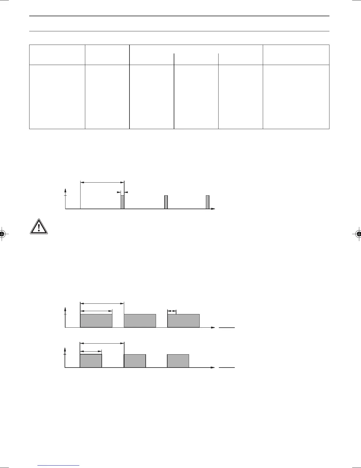
Cycle
Control
variable: 50 %
t
on
Cycle
= 0.50
Control
variable: 80 %
t
on
Cycle
= 0.80
The switching time of the DULCOMETER
®
D1C (solenoid valve) depends on the control variable and the
“min. time” (smallest permitted operating factor of the connected device).
The control variable determines the ratio t
on
/cycle and thus the switching times (see fig. above).
The “min. time” influences the switching times in two situations:
Complete Operating Menu / Description
Cycle
Timer relay
off
on
t
t
on
IMPORTANT
The timer will reset in the event of a power failure.
At the end of the (timer) cycle time the DULCOMETER
®
D1C closes the assigned relay for the duration of
“t on” (timer). “Pause” interrupts the timer.
When the clock is shown in the LC display the timer can be reset to the start of the cycle at precisely this
point using the enter button.
The % figure in the LC display indicates the progress of the current cycle.
Timer relays may be used, e.g. for shock metering or sensor cleaning.
Possible values
Initial value Increment Lower value Upper value Remarks
NOTE
The limit value relay can be defined in such a way as to respond as a control element, i.e. if a
limit value relay closes a circuit, it opens when a pause contact is activated and/or for a
subsequent delay period t
d
(if t
d
is set to > 0 min in “General settings”).
BA_DM_173_03_09_GB.p65 30.03.2009, 12:10 Uhr20