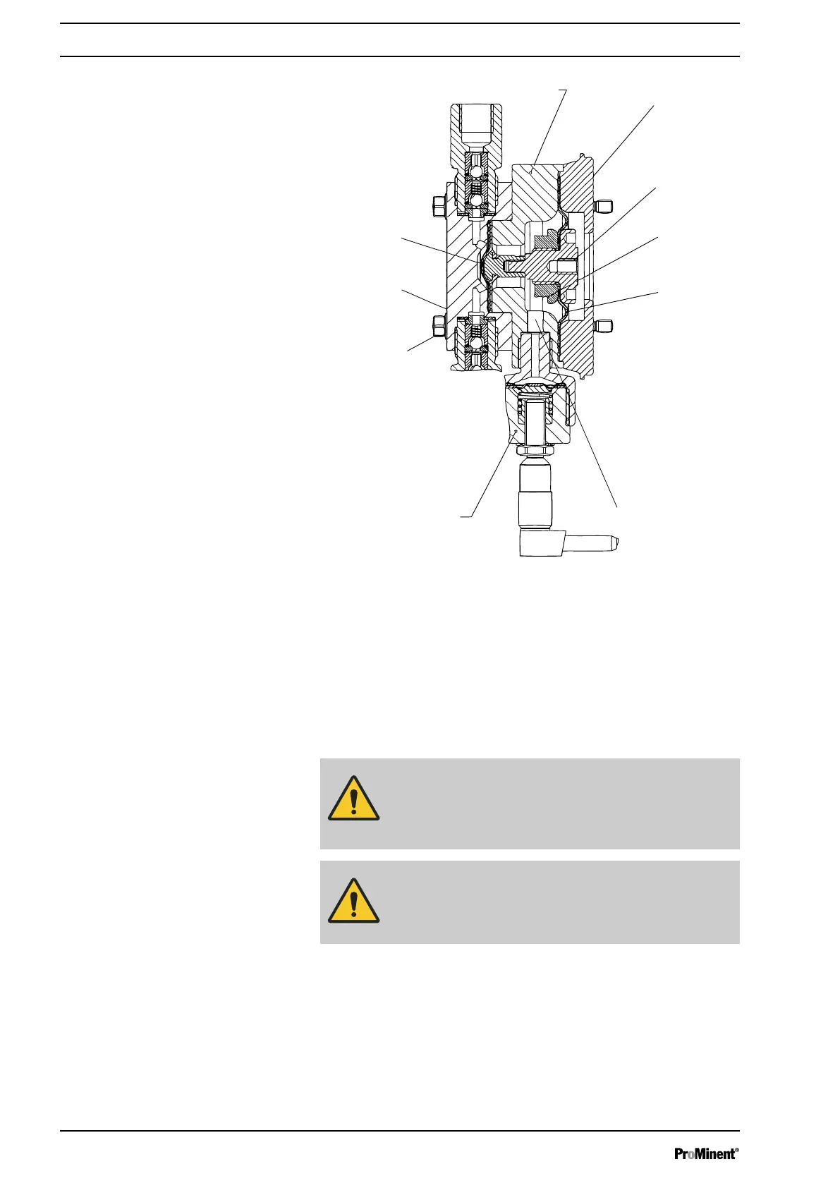
Fig. 4
1 Backplate
2 Adapter
3 Intermediate bushing
4 Additional diaphragms
5 Adapter plate
6 Metering diaphragm
7 Dosing head
8 Fixing bolt
9 Diaphragm rupture sensor
10 Feed channel
CAUTION!
Only above approximately 2 bar system back pres‐
sure is an electrical signal triggered in the event of
diaphragm rupture.
CAUTION!
Once the operating membrane has ruptured, a pre‐
cise metering rate can no longer be guaranteed.
5.5 Metering rate
The stroke length can be continuously adjusted between 100 %
and 10 % using the stroke length control knob (14).
The stroke rate control knob (16) can be used to manually set 0 to
110 (120) strokes/min.
Functional description
16