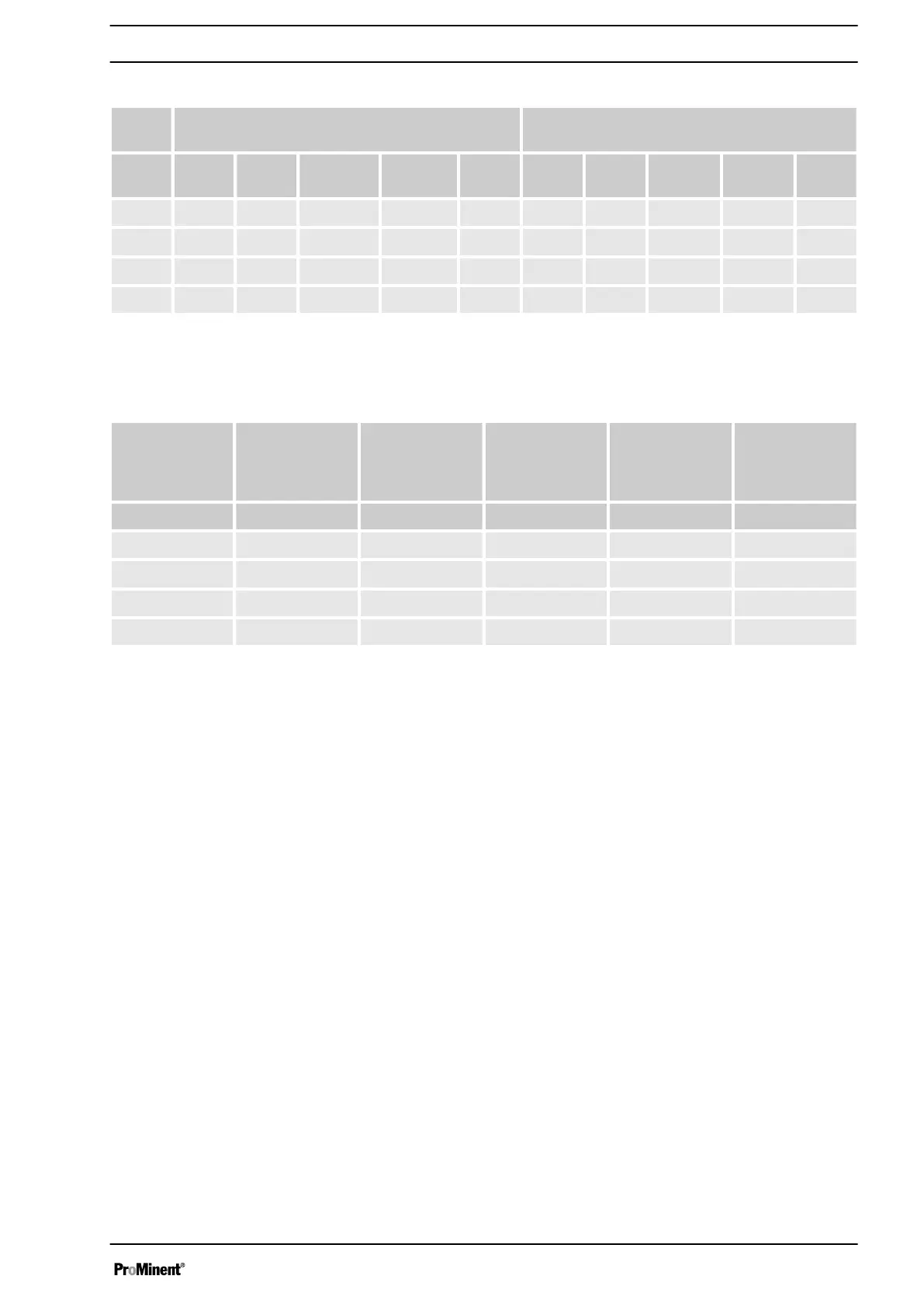
Tab. 9: Metering pumps with self-bleeding dosing head ***
Pump
type
Maximum pump capacity at maximum back
pressure
Maximum pump capacity rate at medium back
pressure
EXBb bar l/h psi gph Ml /
stroke
bar l/h psi gph Ml /
stroke
1601 16 0.66 232 0.174 0.09 - - - - -
1201 12 1.0 274 0.265 0.14 - - - - -
0803 8 2.4 116 0.634 0.33 - - - - -
1002 10 1.8 145 0.476 0.25 - - - - -
*** The given performance data represents guaranteed minimum
values, calculated using water at room temperature
1 gal= 3.78 l
Pump type Stroke rate Connector size
outside dimen‐
sion x inside
diameter
Suction lift* Priming lift** Permissible pri‐
ming pressure,
suction side
EXBb Strokes/min mm m water column m water column bar
1601 120 6x4 - 1.8 0.2
1201 120 6x4 - 2.0 0.2
0803 120 6x4 - 2.8 0.2
1002 120 6x4 - 2.0 0.2
* Suction lift: with filled suction line
** Priming lift: with an empty suction line
14.2 Precision
min.: -5 %, max.: not specified
with max. stroke length and max. back pressure for all material ver‐
sions.
better than ± 2 %
under constant conditions and at least 30% stroke length;
Note the following information:
n All figures refer to dosing measurements with water at 20 °C.
n Constant back pressure, if possible above 1 bar.
n If metering at atmospheric pressure, a back pressure valve
must be used to create a back pressure of at least 1.5 bar
(note the installation examples).
n Wherever possible, lay suction and metering lines on a contin‐
uously rising gradient.
n If the liquid level of the storage tank lies above the pump when
in operating mode, the priming pressure lies against the suc‐
tion side; in this case, the back pressure should be high
enough to ensure a minimum pressure difference of 1.5 bar;
alternatively, use a back pressure valve or a spring-loaded
injection valve with corresponding priming pressure.
Technical data
49