EasyManua.ls Logo

ProSoft Technology MVI56E-MCM User Manual

ProSoft Technology MVI56E-MCM
209 pages
To Next Page IconTo Next Page
To Previous Page IconTo Previous Page
Page #45 background imageLoading...
Page #45 background image
MVI56E-MCM ControlLogix Platform Configuration as a Modbus Master
Modbus Communication Module User Manual
ProSoft Technology, Inc. Page 45 of 209
Label
Description
Enable = 1
The module will send the command every time it goes through the
command list.
IntAddress = 1010
Places the data read from the Slave device into the module at address
1010. IntAddress 1010 of the module memory will be copied into the tag
MCM.DATA.READDATA[10].
Count = 10
Reads 10 consecutive registers from the Slave device.
Node = 1
Issues the Modbus command to node 1 on the network.
Func = 4
Issues Modbus Function Code 4 to Read Input Registers.
DevAddress =20
Function Code 4 DevAddress of 20 will read address 30021
Along with a count of 10, this command reads 30021 to 30030.
2.3.3 Read Coil Status 0x (Modbus Function Code 1)
Modbus Function Code 1 reads the Coils addressed at 0001 to 9999 from a
Slave device. These are bit values that are read using Modbus Function Code 1,
and can be written to using Function Code 5 or 15. Within a Slave device, this is
an individual bit value. Thus, the IntAddress field must be defined down to the bit
level within your MasterCmd.
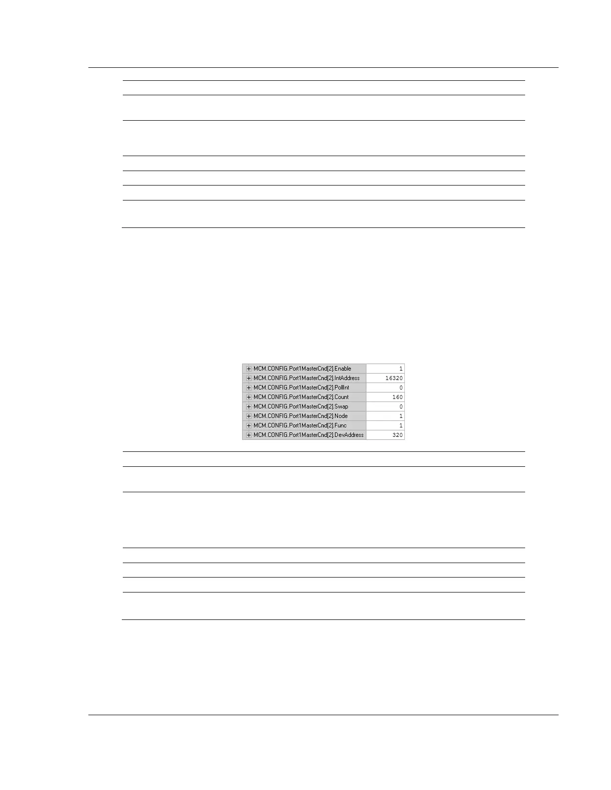
Below is a sample command to read Modbus addresses 0321 to 0480 of node 1
on the Modbus network.
Label
Description
Enable = 1
The module will send the command every time it goes through the
command list.
IntAddress = 16320
Places the data read from the Slave device into the module at address
16320. IntAddress 16320 of the module memory will be copied into the
tag MCM.DATA.READDATA[20] because 16320 represents a bit
address within the memory of the MVI56E-MCM module (16320 / 16 =
register 1020).
Count = 160
Reads 160 consecutive bits from the Slave device.
Node = 1
Issues the Modbus command to node 1 on the network.
Func = 1
Issues Modbus Function Code 1 to Read Coils.
DevAddress = 320
Function Code 1, DevAddress of 320 will read address 0321
Along with a count of 160, this command reads 0321 to 0480.

Table of Contents

Other manuals for ProSoft Technology MVI56E-MCM

Question and Answer IconNeed help?

Do you have a question about the ProSoft Technology MVI56E-MCM and is the answer not in the manual?

ProSoft Technology MVI56E-MCM Specifications

General IconGeneral
VendorProSoft Technology
ModelMVI56E-MCM
CategoryControl Unit
Product TypeCommunication Module
Communication ProtocolModbus
CompatibilityAllen-Bradley ControlLogix
Backplane CompatibilityControlLogix
Relative Humidity5 to 95% non-condensing
Number of Modbus Ports1
Serial Port TypeRS-232/RS-485
Operating Temperature0 to 60°C (32 to 140°F)
Storage Temperature-40 to 85 °C
Module TypeCommunication Module
Backplane Current Draw800 mA @ 5V DC

Summary

Your Feedback Please

Content Disclaimer

Important Safety Information

North America Warnings

Specific safety warnings for operating in North American hazardous locations.

ATEX Warnings and Conditions of Safe Usage

Safety guidelines for use in ATEX-certified hazardous locations.

Battery Life Advisory

Information regarding the module's rechargeable battery and its operational life.

1 Start Here

System Requirements

Minimum hardware and software components needed for module installation and operation.

Deployment Checklist

Questions to consider before configuring the module for project deployment.

Package Contents

List of components included with the MVI56E-MCM module for installation.

Setting Jumpers

Instructions on configuring serial communication mode using module jumpers.

Installing the Module in the Rack

Step-by-step guide for physically installing the MVI56E-MCM into a ControlLogix chassis.

Creating a New RSLogix 5000 Project

Procedure for setting up a new project in RSLogix 5000 for the module.

Import the Ladder Rung

Steps to import the necessary ladder logic into the RSLogix project.

Adding Multiple Modules (Optional)

Instructions for adding additional MVI56E-MCM modules to an existing project.

2 Configuration as a Modbus Master

Overview

Introduction to configuring the module as a Modbus Master device.

ModDef Settings

Configuration of module's data registers for master communication.

Master Command Examples

Illustrative examples of configuring Modbus master commands.

Floating-Point Data Handling (Modbus Master)

Methods for reading and writing floating-point data in Modbus master mode.

Command Control and Event Command

Using commands to control or interrupt normal polling sequences.

3 Configuration as a Modbus Slave

Overview

Introduction to configuring the module as a Modbus Slave device.

ModDef Settings

Configuration of module's data registers for slave communication.

Slave Configuration

Parameters for configuring the module as a Modbus Slave.

Floating-Point Data Handling (Modbus Slave)

Methods for handling floating-point data in Modbus slave mode.

Read and Write Same Modbus Address (Pass Through)

Using Pass-Through mode for direct processor access.

4 Verify Communication

Verifying Master Communications

Methods for checking successful Modbus Master communication.

Verify Slave Communications

Methods for checking successful Modbus Slave communication.

5 Diagnostics and Troubleshooting

Ethernet LED Indicators

Status indications provided by the module's Ethernet port LEDs.

Troubleshooting the LEDs

Steps to resolve issues indicated by module LEDs.

Setting Up ProSoft Configuration Builder

Guide to installing and configuring ProSoft Configuration Builder software.

Connecting Your PC to the Module

Procedures for establishing PC connectivity to the module.

Downloading the Project to the Module

Steps to download configured project files to the module.

Using the Diagnostics Menu in ProSoft Configuration Builder

Navigating the Diagnostics menu within ProSoft Configuration Builder.

Reading Status Data from the Module

Methods for retrieving operational status data from the module.

Configuration Error Codes

Understanding error codes related to module configuration.

6 Reference

Product Specifications

Technical details and features of the MVI56E-MCM module.

Functional Overview

Detailed explanation of the module's functionality and operation.

Cable Connections

Information on connecting serial and Ethernet cables to the module.

MVI56E-MCM Database Definition

Mapping of the module's internal database registers and their content.

MVI56E-MCM Configuration Data

Details on configuration parameters available for the module.

MVI56E-MCM Status Data Definition

Definition of status data fields transferred from the module.

MVI56E-MCM User Defined Data Types

Description of user-defined data types used in module operations.

Modbus Protocol Specification

Reference information on supported Modbus protocol commands.

Using the Optional Add-On Instruction

Guide on utilizing optional logic for Ethernet and clock configuration.

7 Support, Service & Warranty

Contacting Technical Support

Information and procedures for contacting technical support.

Warranty Information

Details regarding the product's warranty terms and conditions.

Related product manuals