MVI56E-MCM ♦ ControlLogix Platform Configuration as a Modbus Slave
Modbus Communication Module User Manual
ProSoft Technology, Inc. Page 61 of 209
With the sample configuration, the following is the layout of the tags and
addressing.
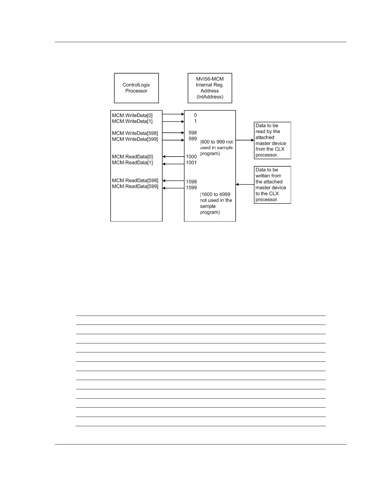
The sample configuration values configure the module database for
WRITEDATA[0 TO 599] to be stored in the module memory at register 0 to 599,
and READDATA[0 TO 599] to be stored in the module memory at registers 1000 to
1599 as shown above.
3.2.1 Modbus Memory Map
Based on the configuration described above, below is the default Modbus
address for the module. Each register within the module can be accessed as a
0xxx bit address, 1xxxx bit address, 3xxxx register address, or 4xxxx register
address.