Reference MVI56E-MCM ♦ ControlLogix Platform
User Manual Modbus Communication Module
Page 184 of 209 ProSoft Technology, Inc.
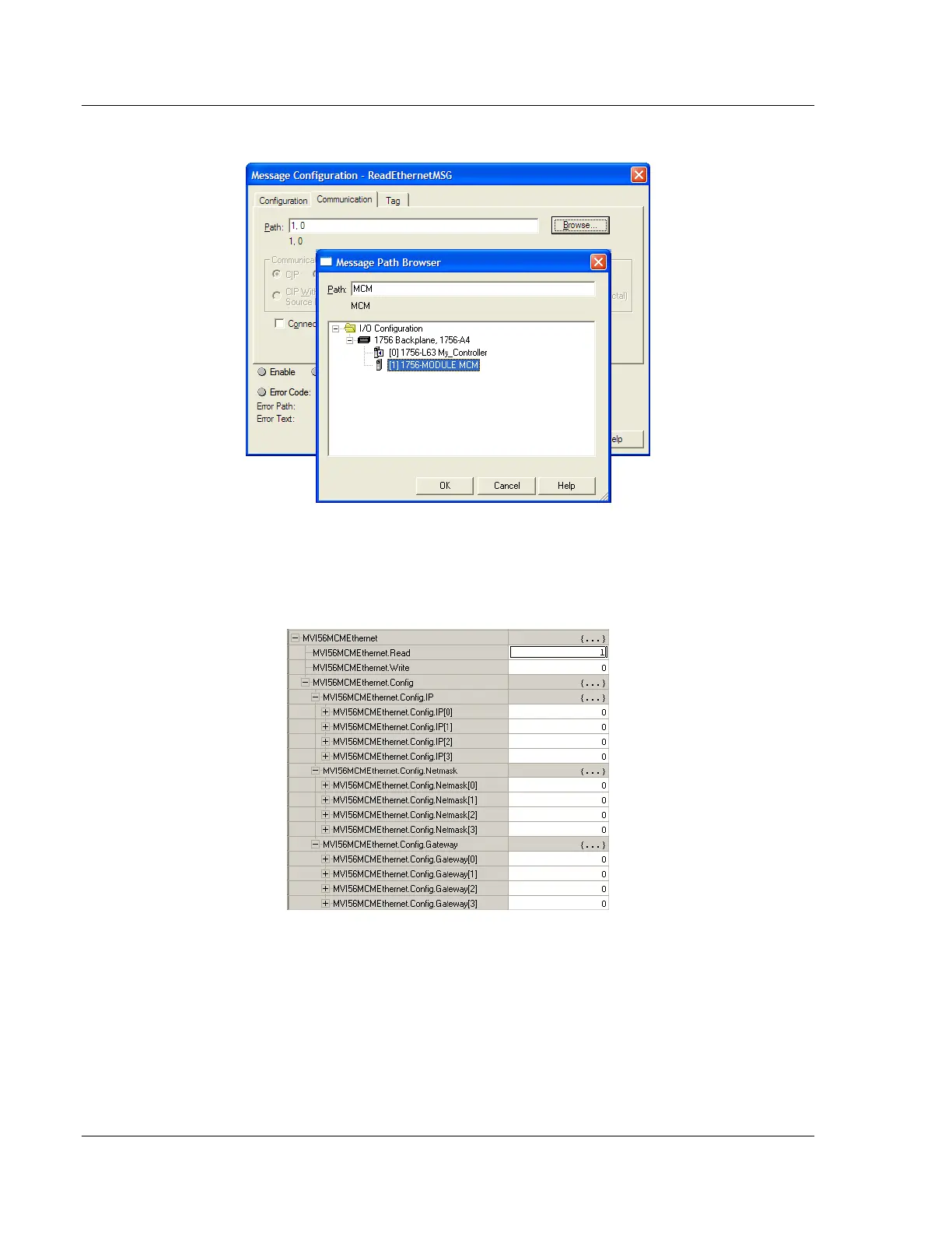
6 Select the module to configure the message path.
6.9.4 Reading the Ethernet Settings from the Module
Expand the MVI56MCMETHERNET controller tag and move a value of 1 to
MVI56MCMETHERNET.READ.