EasyManua.ls Logo

ProSoft Technology MVI56E-MCM User Manual

ProSoft Technology MVI56E-MCM
209 pages
To Next Page IconTo Next Page
To Previous Page IconTo Previous Page
Page #75 background imageLoading...
Page #75 background image
MVI56E-MCM ControlLogix Platform Verify Communication
Modbus Communication Module User Manual
ProSoft Technology, Inc. Page 75 of 209
Transferring the Command Error List to the Processor
You can transfer the command error list to the processor from the module
database. To place the table in the database, set the Command Error Pointer
(MCM.PORT1.CMDERRPTR) parameter to the database location desired.
In the sample ladder, the MCM.PORT1.CMDERRPTR tag is set to a value of 1100.
This will cause the error value of command 0 to be placed at database address
1100. Each command error value occupies one database word. The error value
for command 1 will be in location 1101 and the remaining values in consecutive
database locations.
To transfer this table to the processor, refer to Command Error Codes (page 71).
Make sure that the Command Error table is in the database area covered by the
Read Data (MCM.MODDEF.READSTARTREG and MCM.MODDEF.READREGCNT).
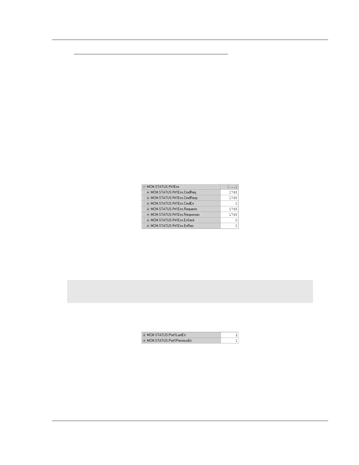
4.1.3 MCM Status Data
Status information can also be obtained from the MVI56E-MCM module by
checking the MCM.STATUS.PRTXERRS location. Below is a sample.
If your system is working correctly, you will see CMDREQ, CMDRESP, REQUESTS,
and RESPONSES all incrementing together. If you see that CMDERR is
incrementing, determine what command is causing the error (using the error
code defined in the previous Command Error Codes (page 71)) and correct the
issue causing the error.
Note: This information is not as detailed as the individual error codes, but they can help to
troubleshoot your application.
Also within the MCM.STATUS location is the parameters for Last Error and
Previous Error, shown below.
This indicates the command index that last generated an error and does not
indicate a command currently in error. In the above example, a value of 2 in
PORT1LASTERR indicates that the last error was generated by
MCM.PORT1MASTERCMD[2]. This does not indicate that this command is
currently in error. The value in MCM.STATUS.PORT1PREVIOUSERR indicates that
before MASTERCMD[2] generated an error, MCM.PORT1.MASTERCMD[1] posted
an error.

Table of Contents

Other manuals for ProSoft Technology MVI56E-MCM

Question and Answer IconNeed help?

Do you have a question about the ProSoft Technology MVI56E-MCM and is the answer not in the manual?

ProSoft Technology MVI56E-MCM Specifications

General IconGeneral
VendorProSoft Technology
ModelMVI56E-MCM
CategoryControl Unit
Product TypeCommunication Module
Communication ProtocolModbus
CompatibilityAllen-Bradley ControlLogix
Backplane CompatibilityControlLogix
Relative Humidity5 to 95% non-condensing
Number of Modbus Ports1
Serial Port TypeRS-232/RS-485
Operating Temperature0 to 60°C (32 to 140°F)
Storage Temperature-40 to 85 °C
Module TypeCommunication Module
Backplane Current Draw800 mA @ 5V DC

Summary

Your Feedback Please

Content Disclaimer

Important Safety Information

North America Warnings

Specific safety warnings for operating in North American hazardous locations.

ATEX Warnings and Conditions of Safe Usage

Safety guidelines for use in ATEX-certified hazardous locations.

Battery Life Advisory

Information regarding the module's rechargeable battery and its operational life.

1 Start Here

System Requirements

Minimum hardware and software components needed for module installation and operation.

Deployment Checklist

Questions to consider before configuring the module for project deployment.

Package Contents

List of components included with the MVI56E-MCM module for installation.

Setting Jumpers

Instructions on configuring serial communication mode using module jumpers.

Installing the Module in the Rack

Step-by-step guide for physically installing the MVI56E-MCM into a ControlLogix chassis.

Creating a New RSLogix 5000 Project

Procedure for setting up a new project in RSLogix 5000 for the module.

Import the Ladder Rung

Steps to import the necessary ladder logic into the RSLogix project.

Adding Multiple Modules (Optional)

Instructions for adding additional MVI56E-MCM modules to an existing project.

2 Configuration as a Modbus Master

Overview

Introduction to configuring the module as a Modbus Master device.

ModDef Settings

Configuration of module's data registers for master communication.

Master Command Examples

Illustrative examples of configuring Modbus master commands.

Floating-Point Data Handling (Modbus Master)

Methods for reading and writing floating-point data in Modbus master mode.

Command Control and Event Command

Using commands to control or interrupt normal polling sequences.

3 Configuration as a Modbus Slave

Overview

Introduction to configuring the module as a Modbus Slave device.

ModDef Settings

Configuration of module's data registers for slave communication.

Slave Configuration

Parameters for configuring the module as a Modbus Slave.

Floating-Point Data Handling (Modbus Slave)

Methods for handling floating-point data in Modbus slave mode.

Read and Write Same Modbus Address (Pass Through)

Using Pass-Through mode for direct processor access.

4 Verify Communication

Verifying Master Communications

Methods for checking successful Modbus Master communication.

Verify Slave Communications

Methods for checking successful Modbus Slave communication.

5 Diagnostics and Troubleshooting

Ethernet LED Indicators

Status indications provided by the module's Ethernet port LEDs.

Troubleshooting the LEDs

Steps to resolve issues indicated by module LEDs.

Setting Up ProSoft Configuration Builder

Guide to installing and configuring ProSoft Configuration Builder software.

Connecting Your PC to the Module

Procedures for establishing PC connectivity to the module.

Downloading the Project to the Module

Steps to download configured project files to the module.

Using the Diagnostics Menu in ProSoft Configuration Builder

Navigating the Diagnostics menu within ProSoft Configuration Builder.

Reading Status Data from the Module

Methods for retrieving operational status data from the module.

Configuration Error Codes

Understanding error codes related to module configuration.

6 Reference

Product Specifications

Technical details and features of the MVI56E-MCM module.

Functional Overview

Detailed explanation of the module's functionality and operation.

Cable Connections

Information on connecting serial and Ethernet cables to the module.

MVI56E-MCM Database Definition

Mapping of the module's internal database registers and their content.

MVI56E-MCM Configuration Data

Details on configuration parameters available for the module.

MVI56E-MCM Status Data Definition

Definition of status data fields transferred from the module.

MVI56E-MCM User Defined Data Types

Description of user-defined data types used in module operations.

Modbus Protocol Specification

Reference information on supported Modbus protocol commands.

Using the Optional Add-On Instruction

Guide on utilizing optional logic for Ethernet and clock configuration.

7 Support, Service & Warranty

Contacting Technical Support

Information and procedures for contacting technical support.

Warranty Information

Details regarding the product's warranty terms and conditions.

Related product manuals