EasyManua.ls Logo

ProSoft Technology MVI56E-MCM User Manual

ProSoft Technology MVI56E-MCM
209 pages
To Next Page IconTo Next Page
To Previous Page IconTo Previous Page
Page #65 background imageLoading...
Page #65 background image
MVI56E-MCM ControlLogix Platform Configuration as a Modbus Slave
Modbus Communication Module User Manual
ProSoft Technology, Inc. Page 65 of 209
3.3 Slave Configuration
Any parameters not mentioned in this section are not used when the module is
configured as a Modbus Master.
Value
Description
Enabled
1= enable port, 0 = disable port
Type
1= Modbus Slave Port
The module also supports a variety of Pass-Through modes. See
Pass-Through Blocks (page 135) for more information.
FloatFlag
As a Slave, emulates Enron/Daniel style floats. See Floating-Point
Data Handling (Modbus Slave) (page 65) for more information.
FloatStart
Register offset in message for floating data point. See Floating-
Point Data Handling (Modbus Slave) (page 65) for more
information.
Protocol
0 = Modbus RTU mode, 1 = Modbus ASCII mode
Baudrate
Sets the baud rate for the port. Valid values for this field are 110,
150, 300, 600, 1200, 2400, 4800, 9600, 19200, 384 or 3840 (for
38,400 baud), 576 or 5760 (for 57,600 baud) and 115,1152, or
11520 (for 115,200 baud)
Parity
0 = None, 1 = Odd, 2 = Even
DataBits
8 = Modbus RTU mode, 8 or 7 = Modbus ASCII mode
StopBits
Valid values are 1 or 2
SlaveID
Valid values are 1 to 247
3.4 Floating-Point Data Handling (Modbus Slave)
In most applications, the use of floating-point data requires no special handling.
1 Copy the data to and from the MVI56E-MCM module with a tag configured as
a data type REAL in the ControlLogix processor.
Each floating-point value will occupy 2 registers on the Modbus network.
Some Master devices use Enron or Daniel Float data. These types of floats
require one Modbus register for each float in the module memory. If your
Master requires this addressing, refer to the following section.
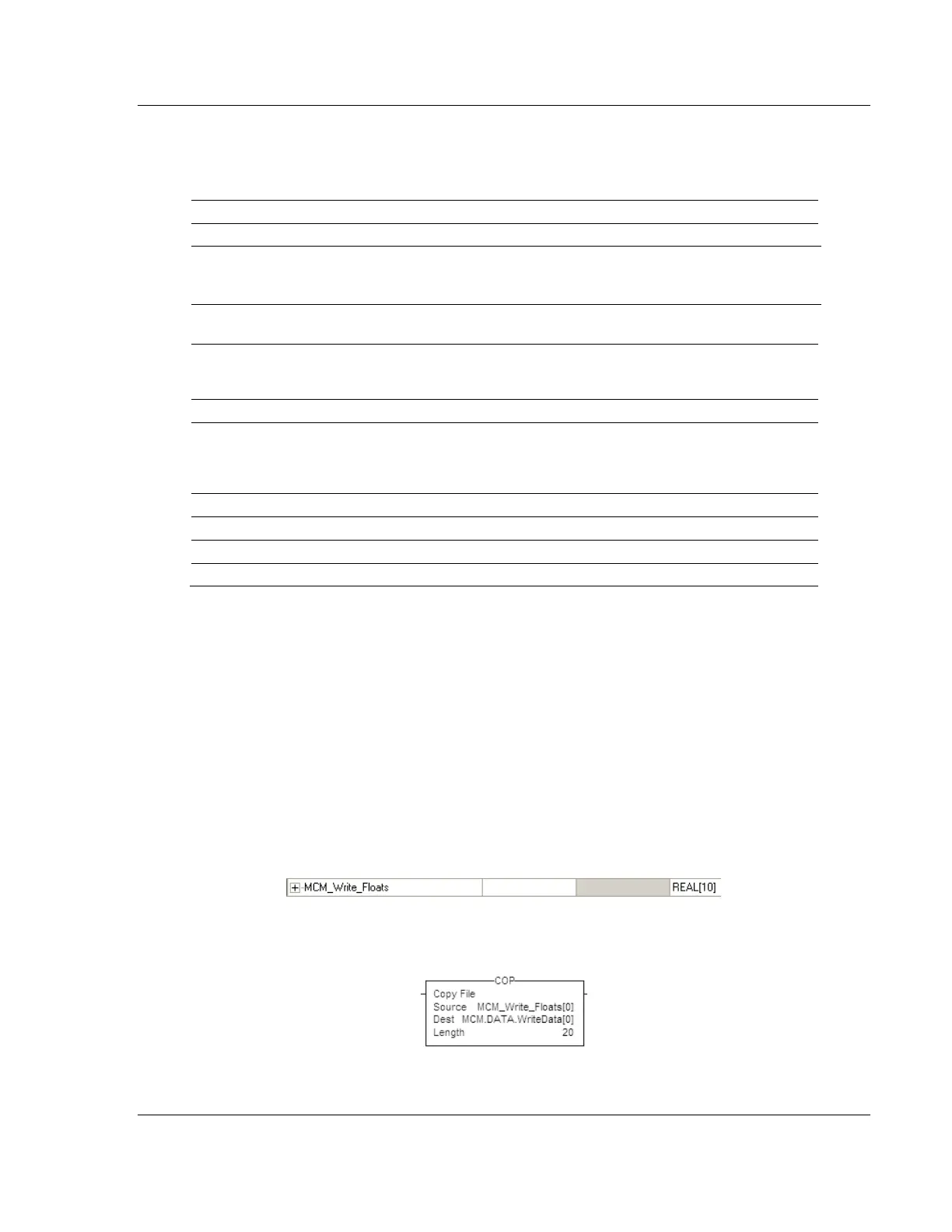
For standard floating-point data handling, the following is an example of
copying 10 floats to the module.
2 First, configure a tag within the ControlLogix processor.
3 Then configure a COP statement within the main routine to copy this tag to
the module's MCM.DATA.WRITEDATA array.

Table of Contents

Other manuals for ProSoft Technology MVI56E-MCM

Question and Answer IconNeed help?

Do you have a question about the ProSoft Technology MVI56E-MCM and is the answer not in the manual?

ProSoft Technology MVI56E-MCM Specifications

General IconGeneral
VendorProSoft Technology
ModelMVI56E-MCM
CategoryControl Unit
Product TypeCommunication Module
Communication ProtocolModbus
CompatibilityAllen-Bradley ControlLogix
Backplane CompatibilityControlLogix
Relative Humidity5 to 95% non-condensing
Number of Modbus Ports1
Serial Port TypeRS-232/RS-485
Operating Temperature0 to 60°C (32 to 140°F)
Storage Temperature-40 to 85 °C
Module TypeCommunication Module
Backplane Current Draw800 mA @ 5V DC

Summary

Your Feedback Please

Content Disclaimer

Important Safety Information

North America Warnings

Specific safety warnings for operating in North American hazardous locations.

ATEX Warnings and Conditions of Safe Usage

Safety guidelines for use in ATEX-certified hazardous locations.

Battery Life Advisory

Information regarding the module's rechargeable battery and its operational life.

1 Start Here

System Requirements

Minimum hardware and software components needed for module installation and operation.

Deployment Checklist

Questions to consider before configuring the module for project deployment.

Package Contents

List of components included with the MVI56E-MCM module for installation.

Setting Jumpers

Instructions on configuring serial communication mode using module jumpers.

Installing the Module in the Rack

Step-by-step guide for physically installing the MVI56E-MCM into a ControlLogix chassis.

Creating a New RSLogix 5000 Project

Procedure for setting up a new project in RSLogix 5000 for the module.

Import the Ladder Rung

Steps to import the necessary ladder logic into the RSLogix project.

Adding Multiple Modules (Optional)

Instructions for adding additional MVI56E-MCM modules to an existing project.

2 Configuration as a Modbus Master

Overview

Introduction to configuring the module as a Modbus Master device.

ModDef Settings

Configuration of module's data registers for master communication.

Master Command Examples

Illustrative examples of configuring Modbus master commands.

Floating-Point Data Handling (Modbus Master)

Methods for reading and writing floating-point data in Modbus master mode.

Command Control and Event Command

Using commands to control or interrupt normal polling sequences.

3 Configuration as a Modbus Slave

Overview

Introduction to configuring the module as a Modbus Slave device.

ModDef Settings

Configuration of module's data registers for slave communication.

Slave Configuration

Parameters for configuring the module as a Modbus Slave.

Floating-Point Data Handling (Modbus Slave)

Methods for handling floating-point data in Modbus slave mode.

Read and Write Same Modbus Address (Pass Through)

Using Pass-Through mode for direct processor access.

4 Verify Communication

Verifying Master Communications

Methods for checking successful Modbus Master communication.

Verify Slave Communications

Methods for checking successful Modbus Slave communication.

5 Diagnostics and Troubleshooting

Ethernet LED Indicators

Status indications provided by the module's Ethernet port LEDs.

Troubleshooting the LEDs

Steps to resolve issues indicated by module LEDs.

Setting Up ProSoft Configuration Builder

Guide to installing and configuring ProSoft Configuration Builder software.

Connecting Your PC to the Module

Procedures for establishing PC connectivity to the module.

Downloading the Project to the Module

Steps to download configured project files to the module.

Using the Diagnostics Menu in ProSoft Configuration Builder

Navigating the Diagnostics menu within ProSoft Configuration Builder.

Reading Status Data from the Module

Methods for retrieving operational status data from the module.

Configuration Error Codes

Understanding error codes related to module configuration.

6 Reference

Product Specifications

Technical details and features of the MVI56E-MCM module.

Functional Overview

Detailed explanation of the module's functionality and operation.

Cable Connections

Information on connecting serial and Ethernet cables to the module.

MVI56E-MCM Database Definition

Mapping of the module's internal database registers and their content.

MVI56E-MCM Configuration Data

Details on configuration parameters available for the module.

MVI56E-MCM Status Data Definition

Definition of status data fields transferred from the module.

MVI56E-MCM User Defined Data Types

Description of user-defined data types used in module operations.

Modbus Protocol Specification

Reference information on supported Modbus protocol commands.

Using the Optional Add-On Instruction

Guide on utilizing optional logic for Ethernet and clock configuration.

7 Support, Service & Warranty

Contacting Technical Support

Information and procedures for contacting technical support.

Warranty Information

Details regarding the product's warranty terms and conditions.

Related product manuals