N93-582-02 Issue 1 NH Page 9 of 28 © Protec Fire Detection plc 2015
4.0 Items Supplied with the Digilite® DL500
• User manual
• Loop commissioning booklet
• Digilite® DL500 spares kit
5.0 Items and Information Required Prior to Commissioning
5.1 Site information required to commission the Digilite® DL500
To ensure rapid and trouble-free commissioning the following information should be supplied to the
commissioning engineer in advance of the proposed commissioning date.
• Address positions of each loop device, exactly matching the site 'as fit' drawings
• Required device types for each address
• Address grouping information
• Device address text ( 20 characters maximum per device )
• Test group text ( 20 characters maximum per group )
• Panel text ( 2 lines of 20 characters maximum )
• Test group programming information (days of the week for each test group, daily test time etc)
• Required Duration test times for central systems
• Network settings ( if the installation uses the Digilite® DL500 TCP/IP Interface )
5.2 PC / Laptop Requirements
The PC used to connect to the Digilite® DL500 and run the PC configuration tool must conform to
the following minimum specification.
• 1 GHz processor
• 2 GB RAM
• 1 GB available hard disk space
• Two available USB 2.0 communication ports
• Windows
®
operating system XP, Vista, Windows
®
7 ( 32 bit or 64 bit ) or
Windows
®
8 ( 32 bit or 64 bit )
• Connection to the internet ( if online software updates are required )
5.3 Software and Hardware Requirements
• Digilite® DL500 Windows Configuration Tool software package
• USB barcode scanner ( CipherLab 1000 CCD, or equivalent )
• T15 Torx™ type security tool ( for removal of the Digilite® DL500 enclosure front cover )
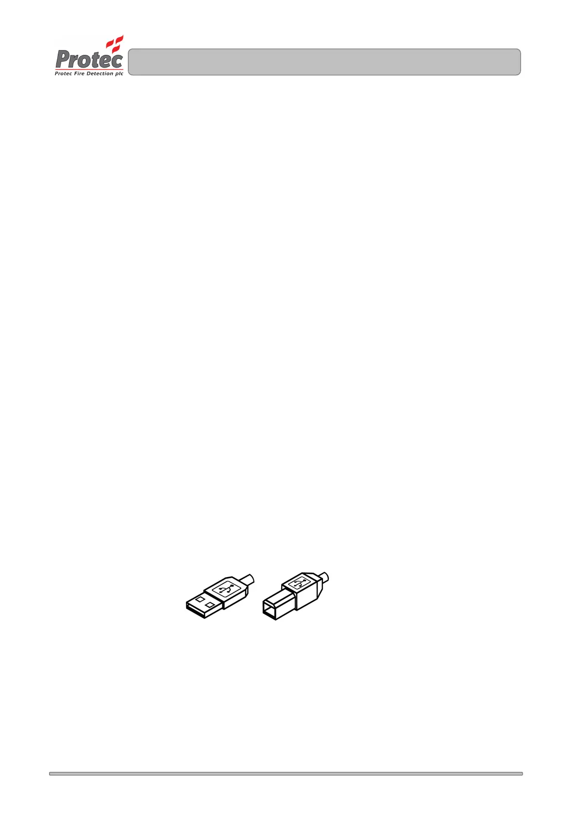
• USB Lead ( Type A male to Type B male, as illustrated below ). 2 metres maximum length.
5.4 I.T Network Setting Details
If the Digilite® DL500 installation includes a TCP/IP Interface (located in the back-box of the panel),
which enables it to communicate with a Protec graphics package, or host the DigiView® Web-server,
various network settings must be obtained from the I.T management of the installation.
See section 14 for full details of the required settings.
TYPE A TYPE B