Page 22
STEP 1
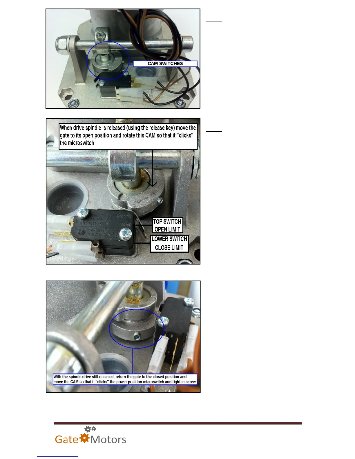
Locate the CAM switches towards the
back of the motor. These are loose
upon manufactuering for ease of
being set. These CAMS rotate around
a pole that is directly connected to the
motors drive spindle shaft.
STEP 2
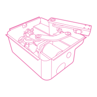
When the cams rotate on the vertical pole
during the gates opening or closing cycles
(the drive spindle turns clockwise / anti-
clockwise) they come into contact with
the metal prong of the limit switchs. This
prong decompresses and physically
“clicks” the switch. This switch will STOP
the motor spindle from turning. If the
timing of the motors is too long, the relays
on control board will try to operate the
motor but the motor will not respond to
the control boards command.
TOP SWITCH = Opening Limit
LOWER SWITCH = Closing Limit
STEP 3
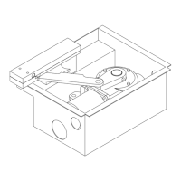
Set the CLOSING CAM first. Release
the motor using the release key and
return the gate to the closed position,
if not already closed, and turning the
LOWER CAM into position as shown
left so that it “clicks” the micro switch.
Fix into position by tightening the grub
screw using a size T10 Allen key.