Page 23
STEP 4
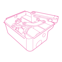
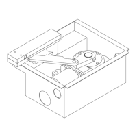
With the drive shaft still released,
move the gate to the open position.
Once in the correct position, rotate
the TOP CAM clockwise so it
“clicks”the microswicth. Tighten with
size T10 Allen Key. The OPENING CAM
should be in a fixed position and must
not move. The motor’s are powerful
and the CAM will move if not
anchored correctly with the Allen key
grub screw.
LEFT HAND MOTOR
Open CAM rotates clockwise
Closing CAM rotates anti-clockwise
RIGHT HAND MOTOR
Open CAM rotates anti-clockwise
Closing CAM rotates clockwise
Please remember that as much as the switches regulate the cycles by physically turning off the
motor to stop it moving further, Gate Stops must still be used to provide adequate resistance for the
motors to detect which will avoid over-running of the spindle drive and will prevent the CAMS
getting stuck/wedged on the metal prongs of the micro switch.
The CAM switches can be re-positioned at any time if the need for a shorter / wider opening angle
arises. Simply follow the steps 1 to 4 and re-perform the Sequential Programming as described in
the Q60AR Control Board for Swing Gates Instruction guide (page 22) to enable the control board to
adjust its motor running time parameters to suit.
Although the operation of the motors is governed by the control board, it is advised to use the micro switches
in conjunction for continued efficient automation of the gates.