Page 47 of 68
Proton Products InteliSENS PD30 Instruction Manual (Issue 1a)
LOGIC INPUTS
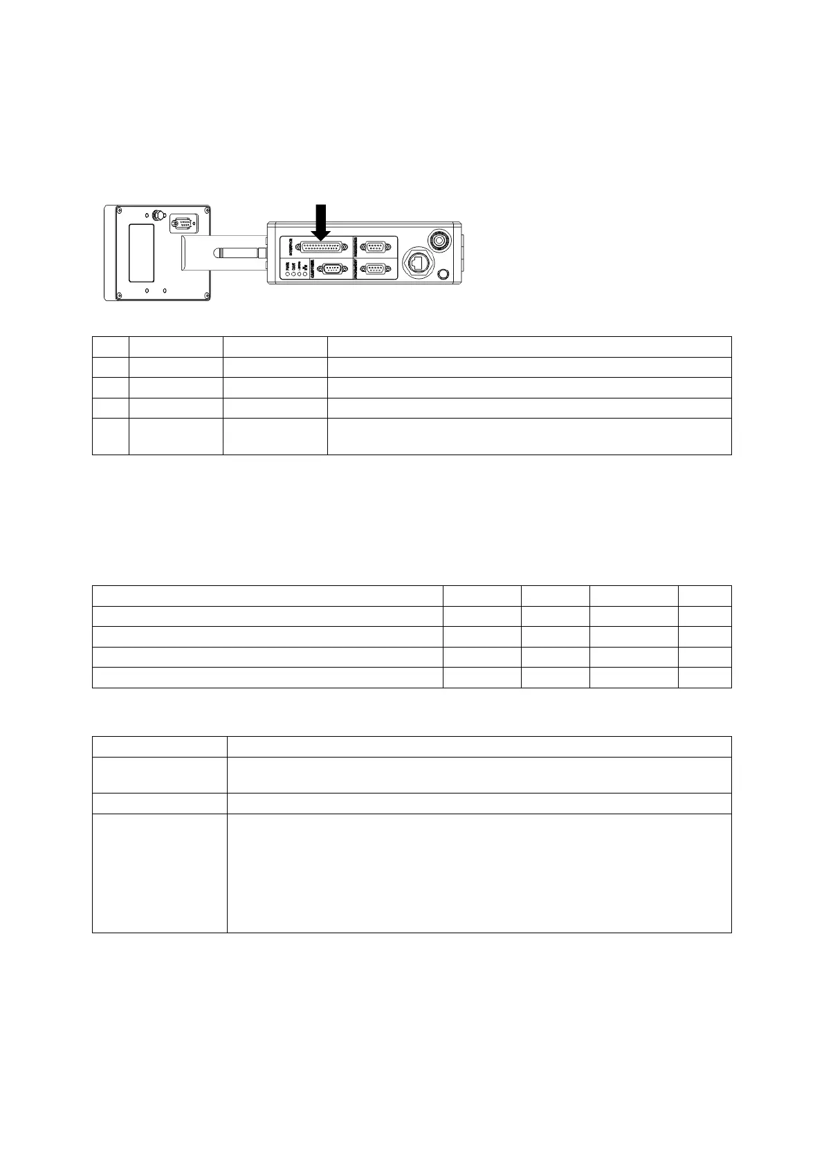
Logic inputs connection
Two logic inputs are fitted as standard and may be accessed through the “INTERFACE” connector.
Connector type: DB25 female (socket)
Ground reference for LIN1 and LIN2.
Ensure that the cable shield is connected to this via the plug
shield connection.
Logic inputs electrical specification
Logic inputs are not isolated from earth.
Inputs are internally pulled up to +15 V via 5.1kΩ resistors; unconnected inputs default to the high
state.
Inputs will source a minimum current of 3mA when externally pulled down to the low state.
Low state (logic 0) input voltage
High state (logic 1) input voltage
Logic inputs can be connected to different types of signal sources as follows:
Mechanical or solid
state relay contact
Connect between logic input and DGND (pin 11).
Connect the pull-down signal to the logic input and ground to DGND (pin 11).
Connect an 820Ω resistor between the logic input and DGND (pin 11) to pull
the input down to 2.5V.
Connect the pull-up signal source to the logic input and ground to DGND
(pin 11).
For 24V signals (such as from a PLC), the power dissipation in the 820Ω
resistor can be reduced by connecting another 820Ω in series between the
pull-up signal source and logic input.