Installation and Operating Instructions
SDC 204 1316BED035-10B-E Date 12/06
- 10 -
6 E
LECTRICAL CONNECTION
You must observe the safety instructions in chapter 1
The device may be opened only if it has been properly
disconnected from the mains and there is no risk of
reconnection.
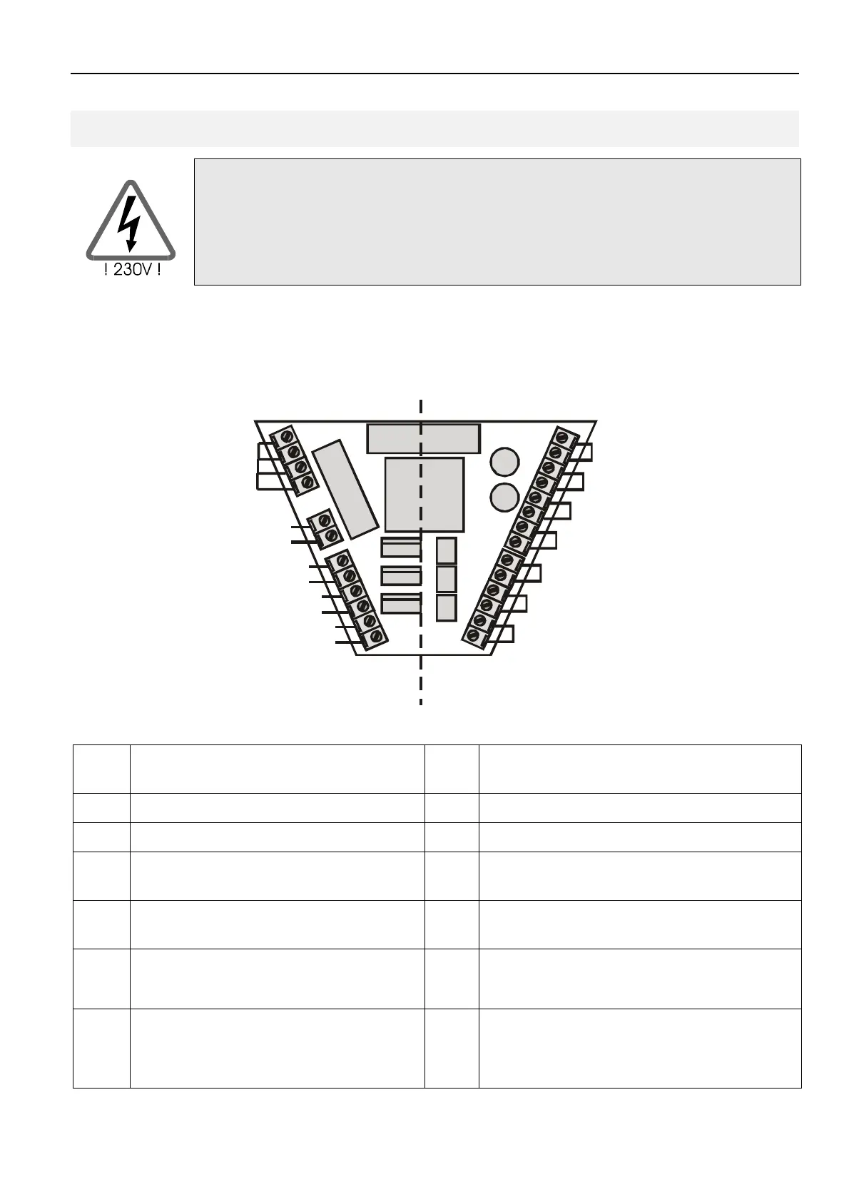
All electrical cables are connected to the
unit in the lower part of the casing. The
terminals on the right-hand side are those
for the (low voltage) connections for sensor
and flow meter. The 230 V connections are
located on the left-hand side. The figure
below shows the terminal field for the
Solareg Vision Plus.
T1
T2
T3
T4
PE
L
N
N
A2
N
A1
S
i
c
h
e
r
u
n
g
Netzspannungs-
bereich
bereich
N
A3
PE Earth wire WM
M
Flow meter
L Phase mains T1 Temperature sensor for collector 1
N Neutral cable for mains T2 Temperature sensor for storage 1
A1 Phase switching output 1 T3 Temperature sensor for collector 2 /
storage 2
A3 Phase switching output 2 T4 Temperature sensor for collector return
line
T5 Temperature sensor for heating /
cooling* or temperature differential
controller - source
T6 Temperature sensor for frost protection*
or temperature differential controller –
target or common measuring point
(autom. deactivated if not connected
* - free choice T1…T6