Installation and Operating Instructions
SDC 204 1316BED035-10B-E Date 12/06
- 11 -
General attachment regulations:
For all attachment wires, cut the wire sheath
to a length of approx. 6 – 8 cm and
unisolate the wires by approx. 10 mm from
the ends.
• In the case of flexible cables, provision
must be made inside or outside the
device for strain relief. The wire ends
must be fitted with wire-end sleeves. If
necessary, PG9 screw fittings can be
used for the feedthrough on the 230 V
side.
• The wires are fed into the device
through the designated openings.
• All earth wires must be fixed in the
terminals indicated with “PE” (Earth
potential).
6.1
230 V connections
The following points must be observed for
the 230 V connections:
• Where there is a fixed mains
connection, it must be possible to
interrupt the mains supply to the control
unit outside the control unit by means of
a switch.
Where the mains connection is effected
by means of wire and plug with earthing
contact, this switch may be dispensed
with.
• The control units are designed for
operation with a 230 V /50 Hz mains
supply. The pumps and valves to be
connected must be designed for this
voltage.
• All earth wires must be connected to the
terminals marked PE.
i
The neutral terminals (N) are electrically
connected and are not switched.
i
The switching outputs (A1/A3) are 230
V closers.
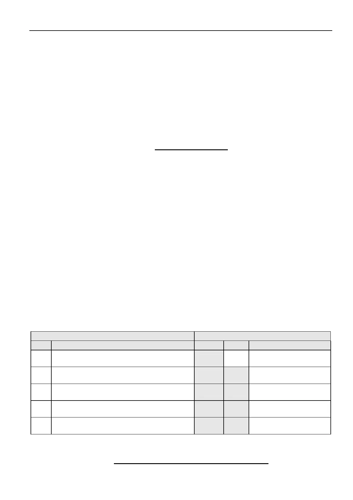
6.1.1 Overview: 230 V connections for Solareg Vision Plus
The table below shows the allocation of
switching outputs for the different system
types. The fields with a grey background are
essential to the basic functions of the
system. The white fields are designed for
optional additional functions:
Systems Outputs
Type
Description A1 A2 A3
0 1 collector array, 1 storage cylinder P1 -
Cooling or thermostat
or diff. controller
1
1 collector array, 2 storage cylinder (pump-
valve)
P1 V1
Cooling or thermostat
or diff. controller
2
1 collector array, 2 storage cylinder (pump-
pump)
P1 P2
Cooling or thermostat
or diff. controller
3
2 collector array, 1 storage cylinder (pump-
valve)
P1 V1
Cooling or thermostat
or diff. controller
4
2 collector array, 1 storage cylinder (pump-
pump)
P1 P2
Cooling or thermostat
or diff. controller
6.2 Attachment of temperature sensor