Installation and Operating Instructions
SDC 204 1316BED035-10B-E Date 12/06
- 12 -
The Solareg Vision Plus devices work with precise platinum temperature sensors of type
PT1000. Between 3 and 4 sensors are required, depending on the scope of function.
Installation/wiring of temperature sensor:
Install the sensors at the requisite places
on the collector and the storage cylinder.
In so doing, ensure good temperature
transmission and, if necessary, use a
thermally conductive paste.
The cables of the temperature sensors
can be extended. For lengths up to 15 m,
a cross-section of 2 x 0.5 mm² is
required; for lengths up to 50 m, a cross-
section of 2 x 0.75 mm² is necessary. In
the case of long connections (collector),
shielded extension cables must be used.
Do not attach the shield on the sensor
side; instead cut it to length and insulate
it.
To protect the collector sensor within the
control unit, the use of a lightning
protection device (accessories) is
recommended.
The temperature sensors are connected
in accordance with the system diagram.
In the case of temperature sensors, there
is no need to observe the polarity of the
two wires.
To protect the collector sensor within the
control unit, the use of a lightning
protection device (accessories) is
recommended.
Sensor wiring must be laid separately
from 230 V wires.
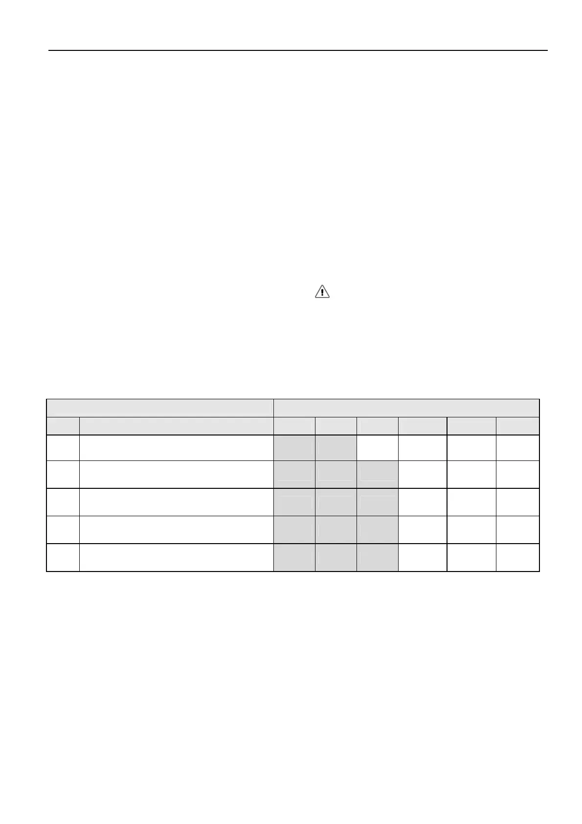
The sensors TTh, Td1 and TFrost can be freely assigned in the „Basic settings“ menu.
System Inscription on the controller
Type
Description T1 T2 T3 T4 T5 T6
0
1 collector array, 1 storage cylinder
TColl1
TCyl1 - TCret TTh Td1
TFrost
Td2
1
1 collector array, 2 storage cylinder
(pump-valve)
TColl1
TCyl1 TCyl2 TCret
TTh Td1
TFrost
Td2
2
1 collector array, 2 storage cylinder
(pump-pump)
TColl1
TCyl1 TCyl2 TCret
TTh Td1
TFrost
Td2
3
2 collector array, 1 storage cylinder
(pump-valve)
TColl1
TCyl1 TColl2
TCret
TTh Td1
TFrost
Td2
4
2 collector array, 1 storage cylinder
(pump-pump)
TColl1
TCyl1 TColl2
TCret
TTh Td1
TFrost
Td2