Page 8
Terminal Connection Details
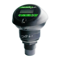
The IMP+ i.s is a 2 wire (loop powered) unit, the terminal connections for IMP+ i.s.
is detailed below. Wiring details are also given on the terminal label under the
access cover.
Terminal 1 + ve: Direct Current (DC) input (12-26VDC) via barrier
Terminal 2 - ve: Ground side
Voltage drop due to i.s. safety Zener barrier
The IMP+ i.s. are 2 wire, 4-20mA loop powered devices. If used with a Zener
barrier (which contains resistors in series with the output) you will experience a
voltage drop across the barrier. The IMP+ i.s. range can be powered from 12-
24VDC, but as the drop across the barrier can be up to 9V depending on the
barrier you are using and the current being drawn (worst case 22mA). You must
also allow for any voltage drops in the cabling from the barrier to the IMP+ i.s..
For example, if an IMP+ i.s. was supplied via a dual Zener barrier with 24V on the
safe side of the barrier then if the unit was drawing 4mA the drop would be
approx. 2V, if the current was 22mA then this would be approx 9V. So as the
IMP+ i.s. requires a minimum of 12V to function correctly, the supply to the IMP+
i.s. at 22mA would be: 24 – 9 = 15V, this means that you could cope with a
voltage drop in the cabling of 3V.
Consideration should be given to any voltage drop in the measuring device.
If you consider say 16/0.2 (0.5mm
2)
conductor, this has a resistance of
39ohms/km, so the maximum length of cable would be as follows:
Maximum voltage drop allowed = 3V
Maximum current = 22mA
So, allowable resistance = 3V / 22mA = 136ohms
Therefore, if you were using 16/0.2 conductors you could use the following
maximum length of cable:
16/0.2 cable resistance = 39ohms/km
You must double this as you have to account for the full length (there and back)
giving 78ohms/km, so,
Absolute maximum cable length = 136 / 78 = 1.7km
In practice allow a reasonable margin.
If you are using a galvanic isolator then you do not have to consider the drop
across the barrier, but you must consider losses in the cable.

 Loading...