Pulsar® Infinity Operation and Installation Manual – Water Treatment 13
3.4 Installation Procedure
Background: The next steps involve installing a loop around the pool
filter where the Pulsar® Infinity Feeder will be located. The pool filter
will create a pressure differential to provide flow through the Pulsar®
Infinity Feeder. This loop is created using the saddle clamps, pitot
tubes, ball valves, tube fittings, and tubing provided with your sys-
tem.
NOTE: Refer to the schematics on pages 11-13 for a pool system
installation and follow the steps below.
NOTE: Before starting installation, determine if the pipes to be
drilled are above or below the pool water level. If they are below
the pool water level, isolation valves must be shut to prevent
backflow through the holes that are being drilled. If isolation
valves are shut properly, some water may drain out of the
drilled holes but will stop once piping is empty.
NOTE: Apply plumbers tape to all male threads to ensure a leak
free connection.
NOTE: Pitot tubes can be installed in either horizontal or verti-
cal pool piping.
3.4.1 Making the inlet connection from the pool to the
feeder (Pre-Filter)
Choose a location on the main pool recirculation piping on the dis-
charge side of the pool pump but upstream of the pool filter(s). Make
sure the pool pump is off and shut isolation valves from the pool pip-
ing so that it is dry.
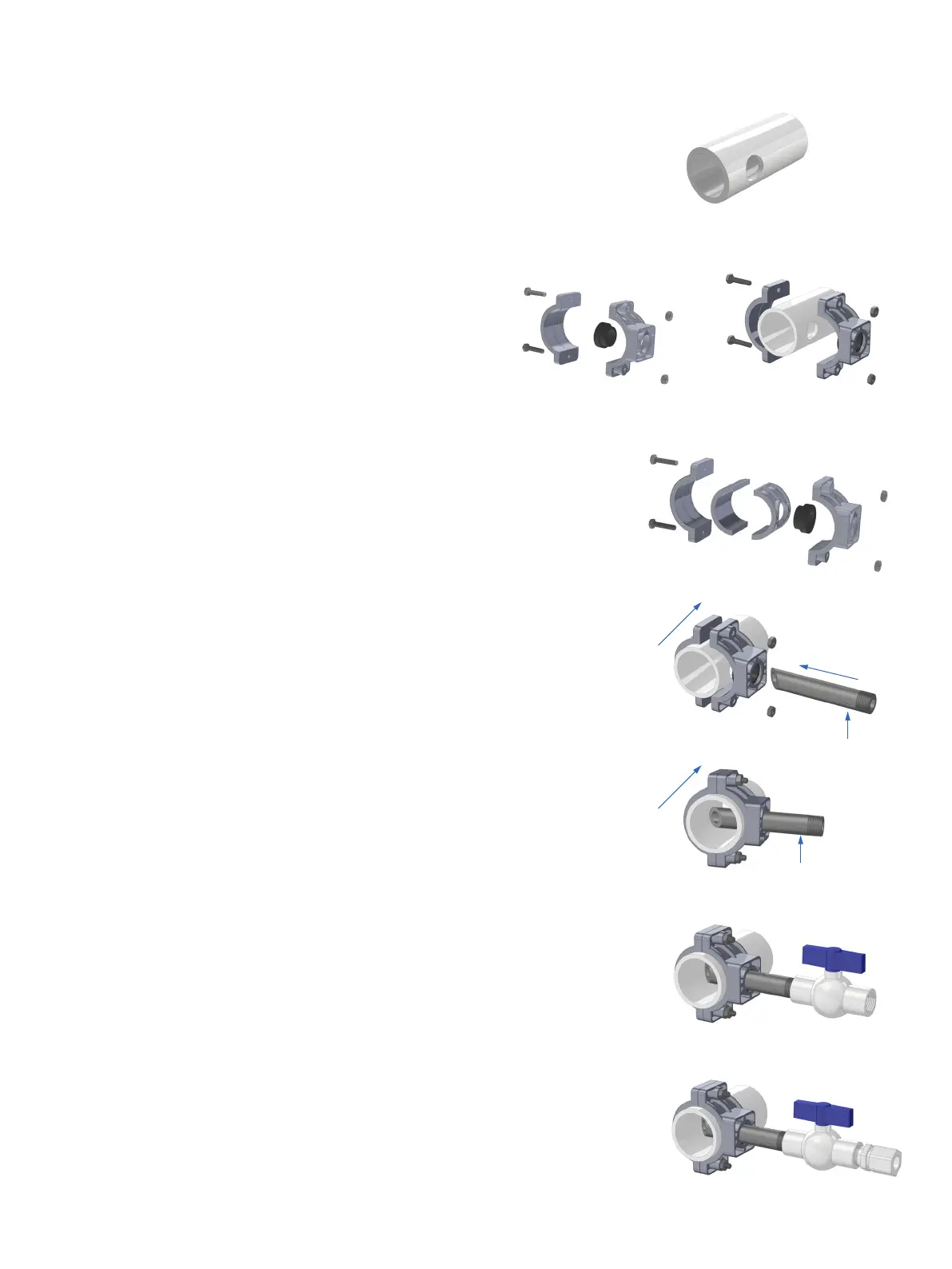
1. Drill 7/8” (22.2 mm)hole anywhere on the top half of the pipe
(figure 1). Caution: Do not drill on the bottom half of the pipe.
Excess debris may enter your feeder.
2. For 2” [50.8 mm] pool pipe, use Assembly A (figure 2a). Do not
yet fully tighten nuts (figure 2b). For 1-1/2” [38.1 mm] pool
pipe, use Assembly B (figure 2c). Refer to Appendix A for Pitot
Tubes for 2 ½” and 3” pool piping.
3. Insert part C (figure 3a). Make sure Pitot tube is fully inserted
prior to tightening saddle clamp (figure 3b).
4. Connect part D, Ball Valve (figure 4).
5. Connect part E, Tubing Connector (figure 5).
Figure 2a
Figure 2c
Figure 1
Figure 3a
Notch facing
upstream
Notch facing
upstream
Flow from
pool
Flow from
pool
Figure 3b
Figure 4
Figure 5
Figure 2b