Pulsar® Infinity Operation and Installation Manual – Water Treatment 14
3.4 Installation Procedure (continued)
3.4.2 Making the chlorine injection connection from the
feeder to the pool (post-filter and heater)
Choose a location on the main pool recirculation piping downstream
of the pool filter(s), and heater (if available), but before the acid or
CO
2
injection point.
1. To make the outlet connection from the feeder to the pool, re-
peat all steps from section 3.4.1 except for step #3. Step #3 is
modified as follows:
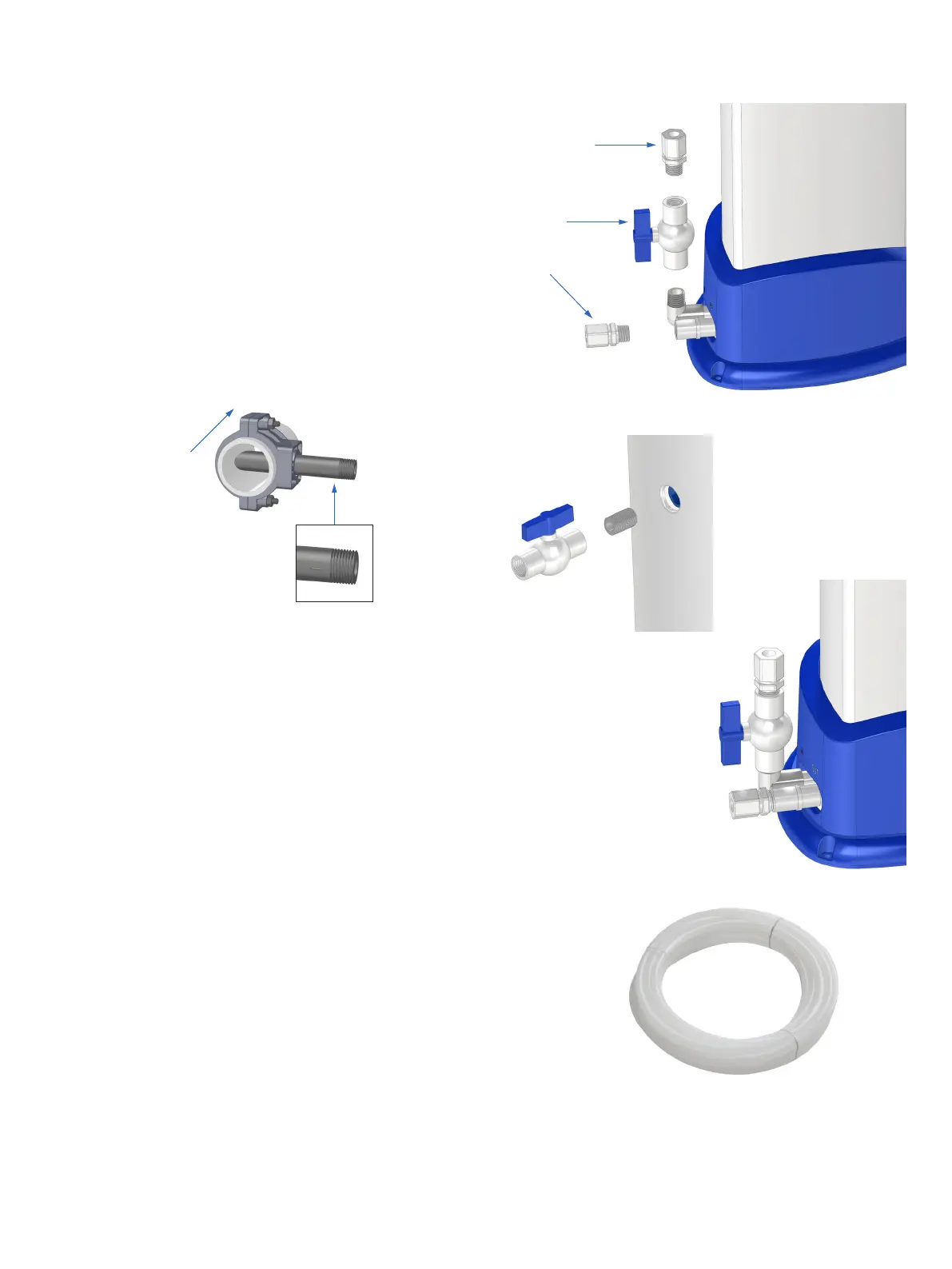
3.4.3 Completing the feeder circulation loop
1. Complete feeder assembly with parts part D, ball valve, and
part E, tubing connector (figure 6).
2. Connect part D, ball valve, and part G, closed nipple to the drain
port to complete the feeder assembly (figure 7a & 7b).
3. Choose a location for the Pulsar® Infinity Feeder that allows
easy access for filling and maintenance.
4. Using the 5/8” [15.9 mm] O.D. tubing, part F (see figure 8),
cut the tubing to size and connect the feeder inlet to the pre-
filter tubing connector installed in step #5 of section 3.4.1, and
connect the feeder outlet to the post-filter tubing connector in-
stalled in step # 1 of section 3.4.2.
This completes your feeder recirculation loop.
Notch facing
downstream
(opposite side of
above view)
Flow from
pool
E
E
D
Figure 6
Figure 7b
Figure 8
Figure 7a