10 QSC Audio Products, LLC
TD-000163-00 Rev. B
1.5 Series description
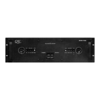
QSC’s ISA Series amplifiers are entry-level professional audio
products for installed sound systems, designed for good, basic
performance and reliability at low price. The series comprises
seven current models—the ISA280, ISA300Ti, ISA450, ISA500Ti,
ISA750, ISA800Ti, and ISA1350—and three discontinued ones—
the ISA300T, ISA500T, and ISA800T.
Outputs for distributed lines
While all ISA models can drive low-impedance speaker loads as
low as 2 ohms per channel, the three ending in “Ti” also have
isolated transformer-coupled outputs for driving 25-, 70-, or 100-
volt lines. The “T” models preceded the “Ti” ones and had non-
isolated autoformer-coupled outputs; other than this distinction,
they are the same as the “Ti” models. Note: For the sake of
brevity, information that pertains to both versions will be
combined in descriptions of the “Ti” models, except where
otherwise noted.
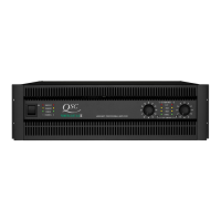
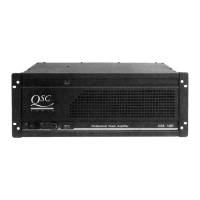
Each model has two audio channels and is three rack spaces tall.
See page 2 for complete specifications.
The ISA280, ISA300Ti, ISA450, and ISA500Ti have single-sided
printed circuit boards. The ISA750, ISA800Ti, and ISA1350 use
double-sided boards.
1.6 Technical descriptions and
theory of operation
Note: Some of these descriptions concern circuitry that is
duplicated in the amplifier’s two channels. For the sake of
simplicity, the descriptions are of Channel 1 only. Components in
Channel 1 have a 3-digit designation with “1” as the first digit;
their equivalents in Channel 2 have a “2” as the first digit,
followed by the same two numerals. For example, R122 and R222
have identical functions in their respective channels.
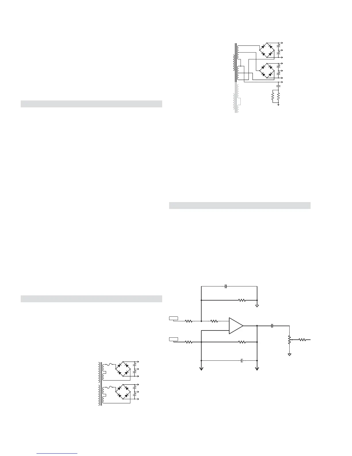
Power supplies
Unlike other recent QSC amplifiers, the ISA line uses strictly
conventional power supplies, with large transformers that operate
at the 50 or 60 Hz frequency of the AC line. The electrical current
in the secondary circuitry is converted to DC through a full-wave
bridge rectifier. The resulting 100 or 120 Hz ripple is filtered out by
large capacitors that also serve as current reservoirs for short-
term, transient demands.
The supply provides a bipolar set
of supply rails for each channel,
with equal quiescent positive and
negative voltages, as shown in
Figure 1.7. Note that unlike many
bipolar supplies for complemen-
tary transistor arrangements, the
secondary windings are not
connected to ground at the center.
+Vcc
-Vcc
+Vcc
-Vcc
Channel 1
Channel 2
+110V
-110V
+55V
-55V
Channel 1
Ch. 1 Center Tap
To Channel 2 Center Tap
12 5W
×2
Ω
0.047 µF
This is because the output
transistors are directly
mounted to the heat sink,
metal-to-metal, to maximize
heat transfer; this grounds
the collectors, requiring
somewhat different output
and power supply arrange-
ments. The grounded-
collector concept is
described later in this
chapter.
In the ISA 750 and ISA 800T, the secondaries are tapped to provide
an intermediate set of bipolar rails for the Class H output circuitry.
Figure 1.8 shows one channel. Class H operation is described later
in this chapter.
The 24-volt cooling fan is driven by a separate DC supply that is
powered by a 20-volt tap on the transformer primary. To minimize
fan noise, the fan speed is controlled by varying its actual DC voltage
in response to the amplifier’s heat sink temperatures. An
optocoupler isolates the fan control circuitry from the thermal
sensors.
Audio circuitry
The audio inputs are balanced to offer a reasonably high amount
of common-mode noise rejection. The input balancing is done
using a single op amp (one half of an NE5532 dual op amp)
arranged as a differential amplifier. The degree of common-mode
rejection is dependent on a close match between the input
resistors (R100 and R101 in Figure 1.9) and between the feedback
resistor and the shunt resistor (R105 and R106). The circuitry uses
1% precision resistors to ensure at least 40 dB of common-mode
rejection.
The feedback and shunt capacitors, C101 and C103, add a first-
order high-frequency roll-off, down 3 dB at 88.4 kHz (over two
2.5K LINEAR
RIGHT ANGLE POT
R106
10.0K
^R_0805
R101
10.0K
^R_0805
R100
10.0K
^R_0805
R105
10.0K
^R_0805
CW
CCW
W
R112
2.5K
A1
R102
1K
^R_0805
+IN_A
-IN_A
C101
180p-5%
^C_0805
C103
180p-5%
C106
47µF NP
3
+
2
-
1
NE5532
U101:1
A1
R113
274
^R_0805
To LM13600 operational
transconductance amp
Figure 1.7
Figure 1.8
Figure 1.9