Technical Service Manual 3
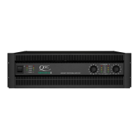
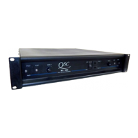
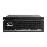
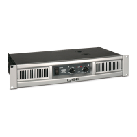
ISA Series Power Amplifiers
Table of Contents
ISA Series Performance Specifications ................................................................................................................................ 5
1. Introduction............................................................................................................................................................................... 7
1.1 Restriction of Hazardous Substances Directive (RoHS) .......................................................................................................................... 7
1.2 Service bulletins ................................................................................................................................................................................................... 7
1.3 The well-equipped service bench ................................................................................................................................................................. 7
1.4 Working with surface-mount components .................................................................................................................................................. 8
Two-terminal components (resistors, capacitors, diodes, etc.) ........................................................................................................................................................................ 8
Three-terminal components (transistors, etc.) ................................................................................................................................................................................................. 8
Multi-pin components (ICs, etc.) ...................................................................................................................................................................................................................... 9
1.5 Series description .............................................................................................................................................................................................. 10
Outputs for distributed lines .......................................................................................................................................................................................................................... 10
1.6 Technical descriptions and theory of operation ..................................................................................................................................... 10
Power supplies .............................................................................................................................................................................................................................................. 10
Audio circuitry ................................................................................................................................................................................................................................................10
Clip detection ................................................................................................................................................................................................................................................ 11
DC protection ................................................................................................................................................................................................................................................ 11
Class H ........................................................................................................................................................................................................................................................... 12
Bridged mono operation and protection ....................................................................................................................................................................................................... 12
Output transformers and autoformers .......................................................................................................................................................................................................... 12
1.7 ISA1350 circuitry ................................................................................................................................................................................................. 13
Class H step drivers ....................................................................................................................................................................................................................................... 13
Bias circuitry .................................................................................................................................................................................................................................................. 13
Muting via the bias network ......................................................................................................................................................................................................................... 13
DC fault protection ........................................................................................................................................................................................................................................ 14
1.8 Revisions made during production ............................................................................................................................................................... 14
ISA750 and ISA800T ..................................................................................................................................................................................................................................... 14
2. Component identification and pinout ..............................................................................................................................15
NE5532AN Dual operational amplifier ......................................................................................................................................................................................................... 15
LM311 Voltage comparator .......................................................................................................................................................................................................................... 15
4N29 Opto-isolator ........................................................................................................................................................................................................................................ 15
LM13600 Dual operational transconductance amplifier .............................................................................................................................................................................. 15
2N5064 Sensitive gate thyristor ................................................................................................................................................................................................................... 15
IRFZ44 TMOS power field effect transistor .................................................................................................................................................................................................. 16
2N3904 (NPN) and 2N3906 (PNP) Small-signal transistors ......................................................................................................................................................................... 16
MJE15032 (NPN) and MJE15033 (PNP) Driver transistors .......................................................................................................................................................................... 16
MAC224 Triac ............................................................................................................................................................................................................................................... 16
2SC5200 (PNP) and 2SA1943 (NPN) Power transistors ............................................................................................................................................................................... 16
3. Troubleshooting: Symptoms, causes, & remedies .......................................................................................................17
3.1 Excessive current draw .................................................................................................................................................................................... 17
Symptoms covered: ....................................................................................................................................................................................................................................... 17
Possible situations: ........................................................................................................................................................................................................................................ 17
3.2 Protection, muting, and turn-on/turn-off delay problems ...................................................................................................................... 17
Symptoms covered: ....................................................................................................................................................................................................................................... 17
Possible situations: ........................................................................................................................................................................................................................................ 17
3.3 Faults with signal present ............................................................................................................................................................................... 18
Symptoms covered: ....................................................................................................................................................................................................................................... 18
Possible situations: ........................................................................................................................................................................................................................................ 18
3.4 Instability .............................................................................................................................................................................................................. 19
Symptoms covered: ....................................................................................................................................................................................................................................... 19
Possible situations: ........................................................................................................................................................................................................................................ 19
3.5 Power supply & rail balancing problems ................................................................................................................................................... 19
Symptoms covered: ....................................................................................................................................................................................................................................... 19
Possible situations: ........................................................................................................................................................................................................................................ 19
Table 1: Bias and current limit adjustments .................................................................................................................................................................................................. 20
4. ISA calibration procedures ................................................................................................................................................21
4.1 Setting bias ........................................................................................................................................................................................................... 21
Tools and resources you will need: ................................................................................................................................................................................................................ 21
Procedure ...................................................................................................................................................................................................................................................... 21
4.2 Setting positive and negative current limits............................................................................................................................................. 21