12 QSC Audio Products, LLC
TD-000163-00 Rev. B
voltage. The triggered SCR will in turn trigger triac Q113, shorting
the output to ground through fuse F100. The fuse will blow,
safeguarding the speaker load from the DC fault.
The output sections of the ISA280, ISA300T, ISA450, and ISA500T
are AC coupled.
Class H
The ISA750 and ISA800Ti utilize a two-tier Class H output section.
It is essentially a Class AB+B circuit but with two sets of bipolar
supply rails. On both the positive and the negative sets of rails, a
comparator circuit, called a “step driver,” compares the audio
signal to the lower rail voltage. When necessary to fully reproduce
the signal’s voltage swing—just before the signal voltage reaches
the lower rail voltage—the step driver turns on a TMOS power FET
to pull the output transistors’ supply rail up from the lower voltage
to the higher one, and then back down again when the signal
allows. By keeping the transistors’ supply rails low whenever
possible, the devices dissipate less unused power and generate
less waste heat, making the amplifier more efficient than a
straight class AB amplifier with the same power points.
The comparators are 311-type ICs: U170 on the positive step and
U171 on the negative. Each one drives a high-gain complementary
transistor pair (2N3904 + 2N3906), which drive the gate of their
respective MOSFET.
The ISA 1350 has a three-tier Class H output section. It works in
much the same way as the two-tier arrangement, but the
additional step further increases the amplifier’s electrical
efficiency.
Bridged mono operation and protection
When the amplifier is operated in bridged mono, its two channels
work in tandem to produce up to twice the voltage swing that a
single channel is capable of. To do this, Channel 2 produces a
signal identical to Channel 1’s, but opposite in polarity—in other
words, a mirror image.
Channel 2’s signal feed (bus BR_MONO_FEED) is an attenuated
version of the signal on Channel 1’s speaker bus. Closing DIP
switch #6 (set to “BRIDGE MONO ON”), connects the
BR_MONO_FEED bus on Channel 1 to the BR_RET bus on Channel
2. The BR_RET bus drives the non-inverting input of op amp
U201:2 directly.
With two channels operating as one, but each having its own
feedback and protection circuitry, it is vital to keep both running as
mirror images. A protection circuit monitors the balance between
Channel 1’s and Channel 2’s signals. Resistors R22 and R23 (R22A,
R22B, R23A, and R23B in the ISA 750 and ISA 800T) are equal in
value and form a voltage divider between the two channel outputs.
If the output signals are mirror images, the voltage at the junction
of the resistors (bus BR_BAL) will be zero. If the signals are not
mirror images—for example, one channel is defunct, distorting, or
reduced in gain—a voltage will appear on BR_BAL. Through DIP
switch 7, the BR_BAL bus becomes bus BR_CUT and feeds the
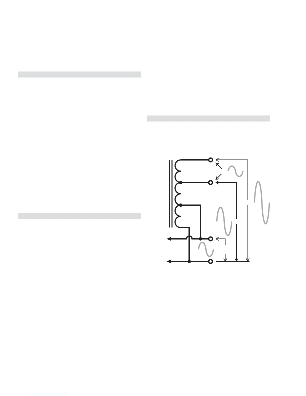
From amplifier
output circuitry
~34V:
8, 4, or 2Ω
70V
100V
25V
AUTOFORMER
bases of transistors Q8 and Q6, which are part of a 4-transistor
circuit across the +15V and -15V rails that supply the op amps and
the input circuitry. If the voltage on BR_CUT goes positive enough
to forward-bias Q8, the transistor’s collector will collapse the +15V
rail. At the same time, the emitter current from Q8 will flow
through R25 and into the emitter of Q7, forward-biasing it, too.
The collector of Q7 will then collapse the -15V rail.
Similarly, if BR_BAL goes sufficiently negative, it will forward-bias
Q6, in turn forward-biasing Q9, and these will collapse the ±15V
rails.
With the rails collapsed, the op amp and the input circuitry will not
function, which will mute the audio.
Output transformers and autoformers
The amplifiers whose model numbers end in “T” have a tapped
autoformer on each channel output. The autoformer allows a
channel to drive distributed speaker lines by converting the output
voltage to an appropriate level. For example, either channel of the
ISA300T (Figure 1.11) can put out a maximum signal level of about
34 volts rms at its low-impedance output terminals, but the
autoformer steps it up to about 70 volts (between the
0
and
70
terminals) or 100 volts (between the
0
and
100
terminals) for
driving lines of those respective voltages. Also, the channel can
drive a 25-volt line connected across the
70
and
100
terminals.
Note that one side of the output is at chassis ground potential.
The “T” models were replaced by the “Ti” ones, which use
transformers to develop the 25-, 70-, and 100-volt outputs (Figure
1.12). The main benefit is the full electrical isolation between the
primary (the amplifier’s internal circuitry) and the secondary (the
distributed loudspeaker line), which some electrical and safety
codes may require.
Figure 1.11