19
Quadra-Fire • EXCURSION-I, EXCURSION-II, EXCURSION-III Installation Manual • 2538-980 Rev. E • 5/19
4
Installation Preparation
Prepare the existing solid fuel masonry or factory built
non-combustible rebox for installation.
A. Cleaning
Prior to installing the gas insert:
• Ensure that the woodburning replace cavity is clean
and free of ash, soot, and other debris.
B. Flue Damper
Fully lock the solid fuel replace’s ue damper in the open
position, OR completely remove it.
C. Gas Line
Note: If the factory built replace has no gas access hole
provided, an access hole of 1 inch (25 mm) diameter or
less may be drilled through the lower sides or bottom of the
rebox in a proper workmanship - like manner. This access
hole must be plugged with non-combustible insulation after
the gas supply line has been installed.
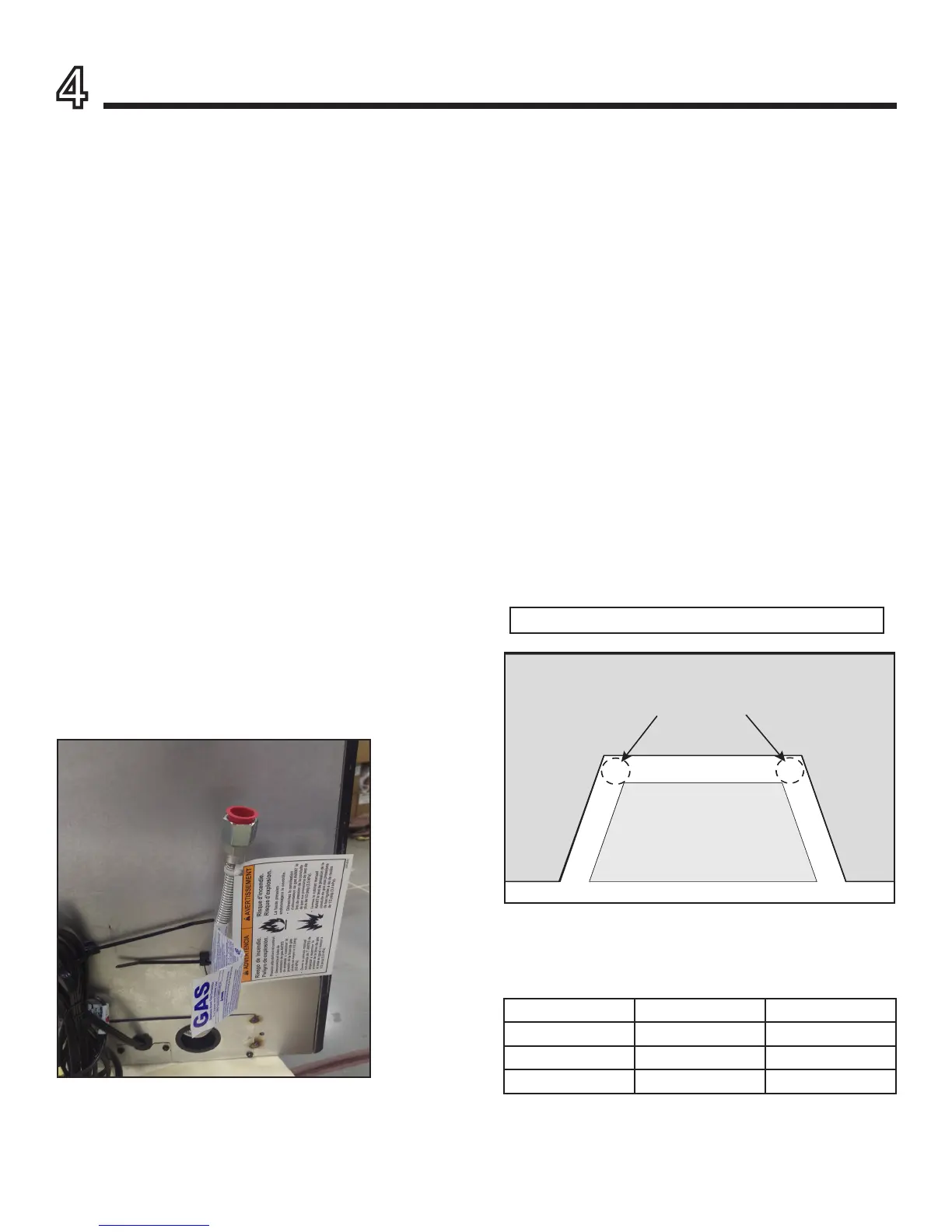
• Install gas line to the factory provided ex line. See
Figure 4.1.
• Check local codes and gas line sizing requirements
following NFPA54. See Section 7.
• It is recommended that extra length of gas line be
installed within the existing wood burner or masonry
replace to allow removal of the insert for future servicing
needs.
D. Fireplace Conversion Notice
The replace conversion notice is included in the appliance
manual bag. Permanently attach the label with the follow-
ing warning to the inside lower back of the replace rebox
into which the insert is being installed. Silicone or mechani-
cal fasteners may be required to properly secure the label.
WARNING! Risk of Fire! This replace has been con-
verted for use with a gas replace insert only and cannot
be used for burning wood or solid fuels unless all original
parts have been replaced, and the replace re-approved
by the authority having jurisdiction.
E. Electrical Outlet Box
An outlet box may be installed in a bottom back corner of
the existing solid fuel masonry or factory built replace
to power the appliance. Each unit ships standard with a
cord assembly to permit blowers or other optional acces-
sories to be used. The accessories plug into the new out-
let box or may be routed out onto the hearth to a nearby
outlet.





 To Next Page