QUANTECH
160
FORM QTC3-NM1
ISSUE DATE 08/03/2022
SECTION 8 – UNIT OPERATION
LEAVING CHILLED LIQUID SYSTEM LEAD/
LAG AND COMPRESSOR SEQUENCING
A Lead/Lag option may be selected to help equalize
average run hours between systems with 2 refriger-
ant systems. This may be programmed under the OP-
TIONS key. Auto Lead/Lag allows automatic Lead/
Lag of the two systems based on average run hours of
the compressors in each system. Manual Lead/Lag se-
lects specifically the sequence which the microproces-
sor starts systems.
On a hot water start, once a system starts, it will turn
ON all compressors before the next system starts a
compressor. The microprocessor will sequence com-
pressors within each circuit to maximize individual
compressor run time on individual compressors within
a system to prevent short cycling.
Each compressor in a system will be assigned an arbi-
trary priority number 1, 2, or 1, 2, 3. The non-running
compressor within a system with the lowest priority
number will always be the next compressor to start.
The running compressor with priority number 1 will al-
ways be the next to shut OFF. Whenever a compressor
is shut OFF, the priority numbers of all compressors
will be decreased by 1 with wrap-around. This control
scheme assures the same compressor does not repeat-
edly cycle ON and OFF.
Once the second system starts a compressor on a 2 sys-
tem chillers, the microprocessor will attempt to equally
load each system as long as the system is not limit-
ing or pumping down. Once this occurs, loading and
unloading will alternate between systems, loading the
lead system first or unloading the lag system first.
RETURN CHILLED LIQUID CONTROL
(Can be used on Dual System 4, 5, and 6 Comp
Units Only)
Return chilled liquid control is based on staging the
compressors to match the cooling load. The chiller
will be fully loaded when the return water temperature
is equal to the Cooling Setpoint plus the Range. The
chiller will be totally unloaded (all compressors OFF)
when the return water temperature is equal to the Cool-
ing Setpoint (See sample in Table 21 on page 159).
At return water temperatures between the Cooling
Setpoint and Cooling Setpoint plus Range, compres-
sor loading and unloading will be determined by the
formulas in Table 22 on page 159.
Return Chilled Liquid Control MUST
only be used when constant chilled liquid
ow is ensured.
The range MUST always be programmed
to equal the temperature drop across
the evaporator when the chiller is “fully
loaded”. Otherwise, chilled liquid tem-
perature will over or under shoot. Variable
ow must never be used in return chilled
liquid mode.
Normal loading will occur at intervals of 60 s accord-
ing to the temperatures determined by the formulas.
Unloading will occur at a rate of 30 s according to the
temperatures determined in the formulas used to calcu-
late the ON and OFF points for each step of capacity.
The return chilled liquid setpoint is programmable
from 40°F to 70°F (4.4°C to 21.1°C) in water chilling
mode and from 10°F to 70°F (-12.2°C to 21.1°C) in
glycol chilling mode. In both modes, the cooling range
can be from 4°F to 20°F (2.2° to 11.1°C).
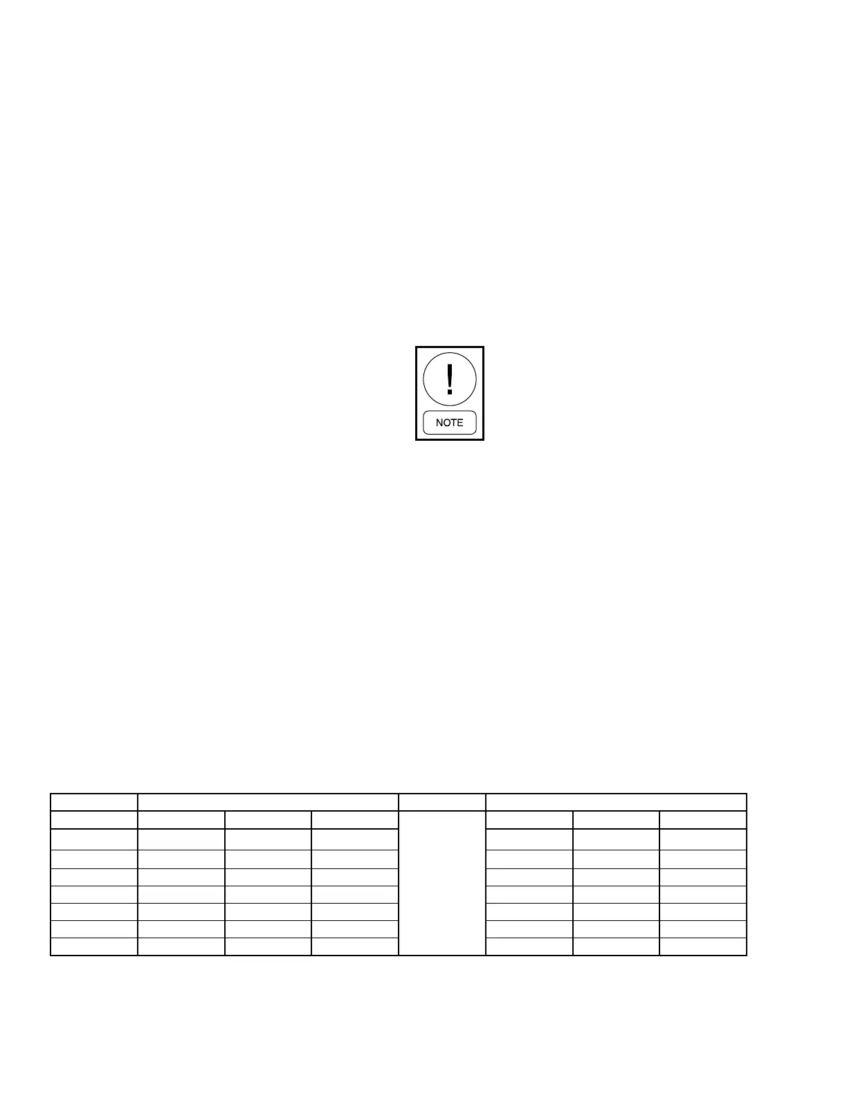
TABLE 23 - LEAD/LAG RETURN CHILLED LIQUID CONTROL FOR 4 COMPRESSORS (6 STEPS)
LEAD SYSTEM LAG SYSTEM
STEP COMP 1 COMP 2 -
SEE NOTE 1
SEE NOTE 2
SEE NOTE 3
COMP 1 COMP 2 -
0
OFF OFF - OFF OFF -
1
ON + HG OFF - OFF OFF
-
2 ON OFF - OFF OFF -
3 ON OFF - ON OFF -
4 ON ON - OFF OFF -
5 ON ON - ON OFF -
6 ON ON - ON ON -
NOTES:
1. Step is Hot Gas Bypass and is skipped when loading occurs. Hot Gas Bypass operation is inhibited during pumpdown. For Leaving
Chilled Liquid Control the Hot Gas Bypass solenoid is energized only when the lead compressor is running and the LWT < SP, the
Hot Gas Bypass solenoid is turned o when the LWT more than SP + CR/2.
2. Step 3 is skipped when loading occurs.
3. Step 4 is skipped when unloading occurs.