159
QUANTECH
FORM QTC3-NM1
ISSUE DATE 08/03/2022
SECTION 8 – UNIT OPERATION
8
TABLE 21 - SAMPLE COMPRESSOR STAGING FOR RETURN WATER CONTROL
COMPRESSOR STAGING FOR RETURN WATER CONTROL
4 COMPRESSOR
COOLING SETPOINT = 45°F (7.2°C) RANGE = 10°F (5.6°C)
# OF COMP ON 0 * 1+HG 1 2 3 4
RWT
45°F
(7.2°C)
46.25°F
(7.9°C)
47.5°F
(8.6°C)
50.0°F
(10.0°C)
52.5°F
(11.4°C)
55.0°F
(12.8°C)
*Unloading only
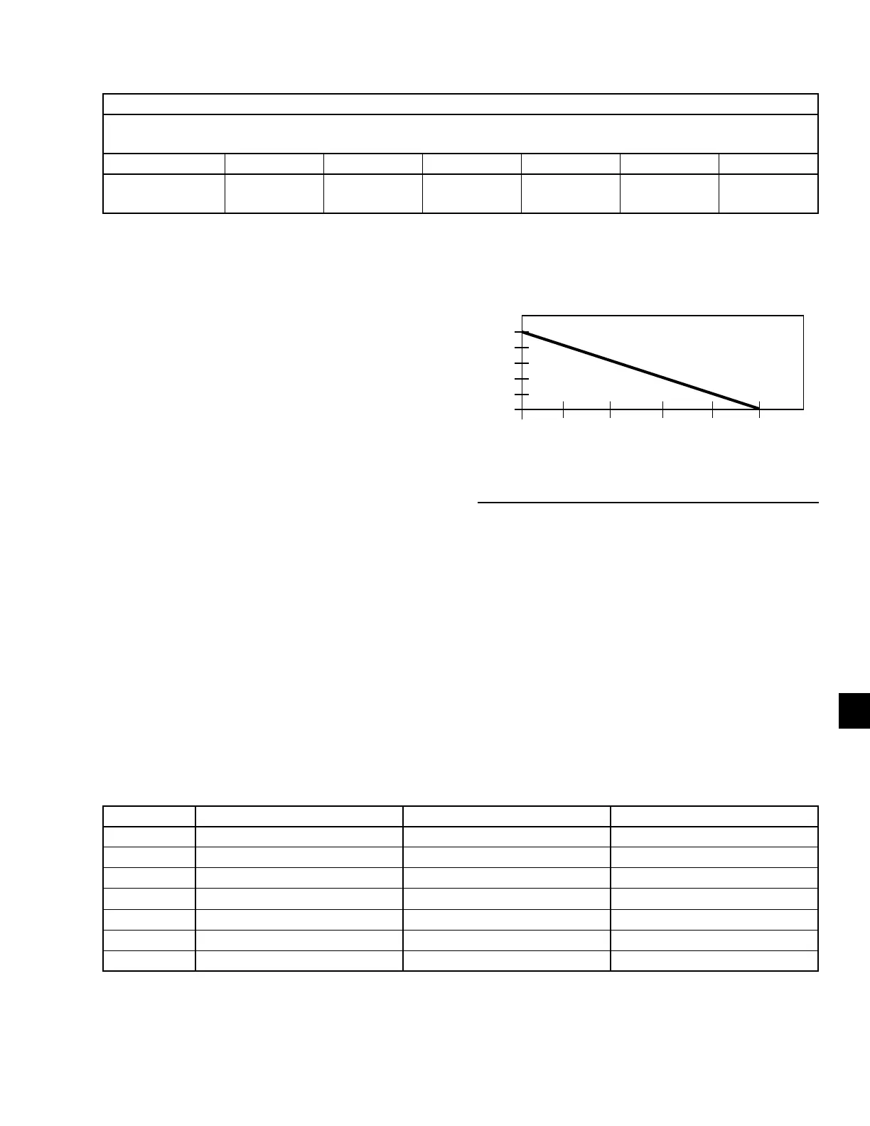
0 1 2 3 4 5
LAST RUN TIME OF LEAD SYSTEM (MINUTES)
ADJUST (DEG. F)
6
5
4
3
2
1
0
FIGURE 31 - SETPOINT ADJUST
LD11415
LEAVING CHILLED LIQUID CONTROL
OVERRIDE TO REDUCE CYCLING
To avoid compressor cycling the microprocessor will
adjust the setpoint upward temporarily. The last run
time of the system will be saved. If the last run time
was greater than 5 min, no action is to be taken. If the
last run time for the lead system was less than 5 min,
the microprocessor will increase the setpoint high limit
according to the chart at right, with a maximum value
allowed of 50°F (see Figure 31 on page 159).
If adding the setpoint adjust value to the setpoint high
limit causes the setpoint high limit to be greater than 50
°F, the setpoint high limit will be set to 50 °F, and the
difference will be added to the setpoint low limit.
Once a system runs for greater than 5 min, the setpoint
adjust will be set back to 0. This will occur while the
system is still running.
TABLE 22 - RETURN CHILLED LIQUID CONTROL FOR 4 COMPRESSORS (6 STEPS)
*STEP COMPRESSOR COMPRESSOR ON POINT COMPRESSOR OFF POINT
0 0 SETPOINT SETPOINT
1 1 W/HGB SP + CR/8
1
SETPOINT
2 1 NO HGB SP + CR/4 SP + CR/8
3 2 SP + 2*CR/4
2
SP + CR/4
4 2 SP + 2*CR/4 SP + CR/4
3
5 3 SP + 3*CR/4 SP + 2*CR/4
6 4 SP + CR SP + 3*CR/4
NOTES:
1. Step 1 is Hot Gas Bypass and is skipped when loading occurs. Hot Gas Bypass operation is inhibited during Pumpdown.
2. Step 3 is skipped when loading occurs.
3. Step 4 is skipped when unloading occurs.
* STEP can be viewed using the OPER DATA key and scrolling to COOLING DEMAND.