GV320 User manual
TRACGV320UM001 - 10 -
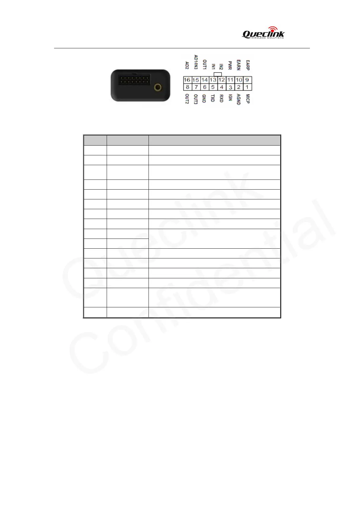
Figure 2. The 16 PIN connector on the GV320
Table 4. Description of 16 PIN Connections
Index Description Comment
1 MICP Single end, 2-2.2k microphone, internal bias
2 AGND Analog ground
3 IGN Ignition input, positive trigger
4 RXD UART RXD, RS232
5 TXD UART TXD, RS232
6 GND Power and digital ground
7 OUT3 Open drain, 150mA max
8 OUT2 Open drain, 150mA max
9 EARP
Differential output, 32ohm 1/4w speaker
10 EARN
11 PWR External DC power input, 8-32V
12 IN2 Digital input, negative trigger
13 IN1 Digital input, negative trigger
14 OUT1 Open drain, 150mA max ,with latch circuit
15 AD1/IN3
Multifunction input, analog or digital input
0-16V
16 AD2 Analog input 0.3-16v