GV320 User manual
TRACGV320UM001 - 16 -
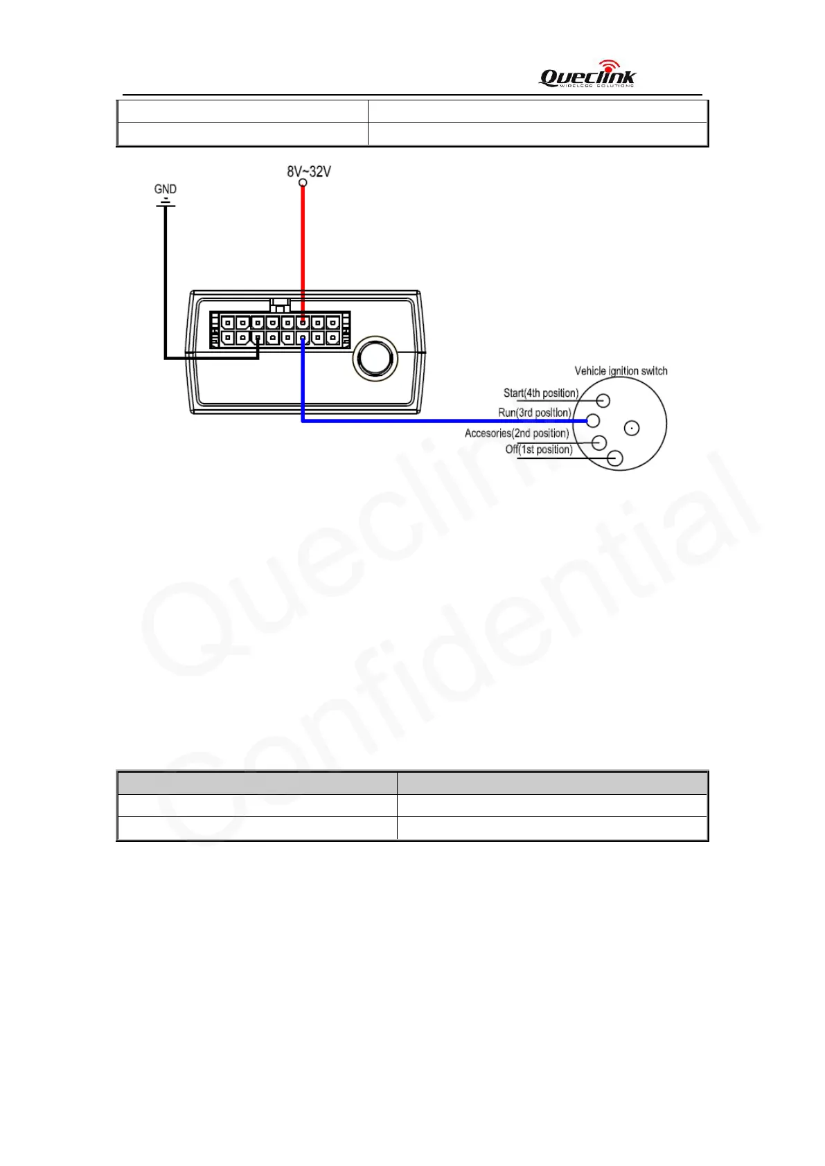
Active 5.0V to 32V
Inactive 0V to 3V or Open
Figure 10. Typical Ignition Detection
IGN (Pin3)is used for ignition detection. It is strongly recommended to connect this pin to
ignition key “RUN” position as shown up.
An alternative to connecting to the ignition switch is to find a non permanent power source
that is only available when the vehicle is running. For example the power source for the
FM radio.
IGN signal can be configured to start transmitting information to backend server when
ignition is on; and enter power saving mode when ignition is off.
There are three general purpose digital inputs on GV320. They are all negative trigger.
Table 8. Electrical Characteristics of the digital inputs
Logical State Electrical Characteristics
Active 0V to 0.8V
Inactive Open
The following diagram shows the recommended connection of a digital input.
3.9. Digital Inputs