GV320 User manual
TRACGV320UM001 - 19 -
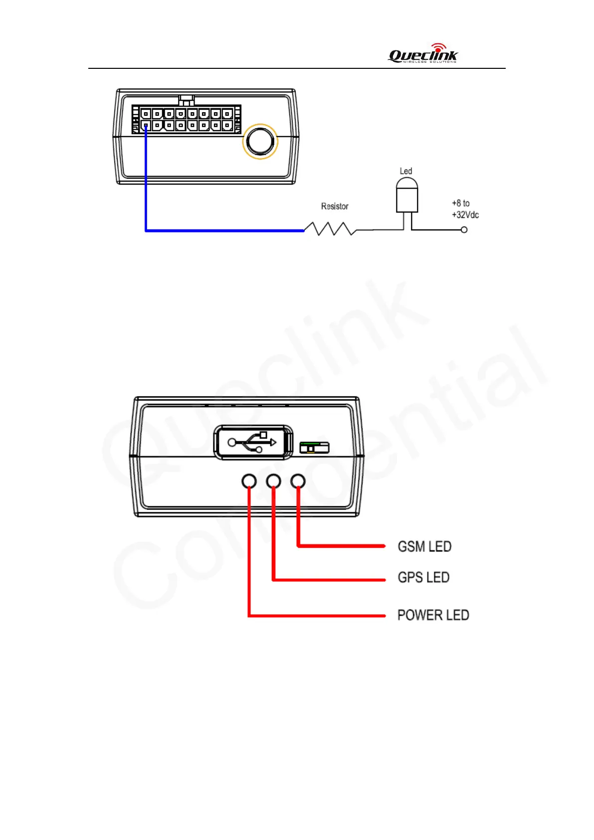
Figure 15. Typical Connection with LED
Note:
1 - OUT1 will latch the output state during reset.
2- All outputs are internally pulled up to PWR pin by a diode. So no external flyback diode
is needed when the output is connected to an inductive load.
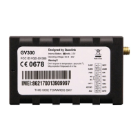
Figure 16. GV320 LED on the Case
Table 10. Definition of Device status and LED
3.12. Device Status LED