GV320 User manual
TRACGV320UM001 - 15 -
Table 6. GPS Antenna Specification
GPS antenna: Frequency: 1575.42MHz
Bandwidth: >5MHz
Beam width: >120 deg
Supply voltage: 2.7V-3.3V
Polarization: RHCP
Gain: Passive: 0dBi min
Active: 15dB
Impedance: 50Ω
VSWR: <2
Noise figure: <3
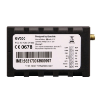
PWR (PIN12) / GND (PIN6) are the power input pins. The input voltage range for this
device is from 8V to 32V. The device is designed to be installed in vehicles that operate on
12V or 24V systems without the need for external transformers.
Figure 9. Typical Power Connection
Table 7. Electrical Characteristics of Ignition Detection
Logical State Electrical State
3.6.1. GPS Antenna Specification
3.7. Power C
3.8. Ignition Detection