M10 Hardware Design
M10_HD_V3.0 - 30 -
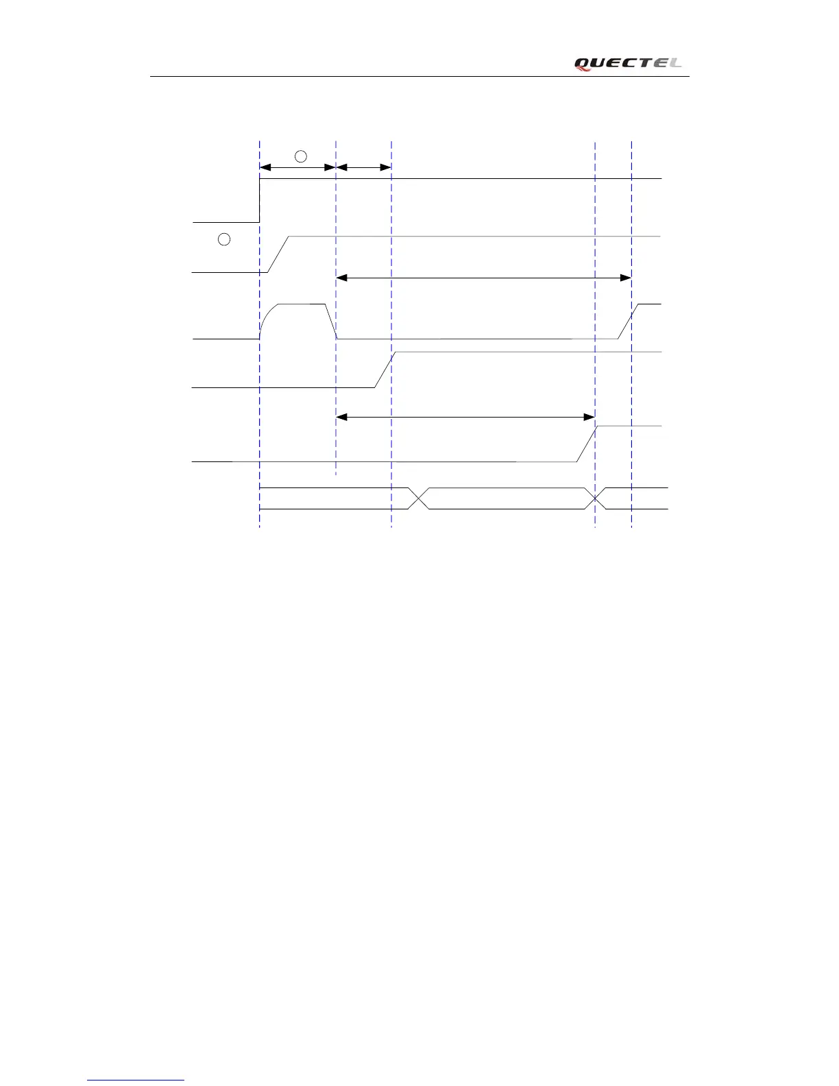
The power on scenarios is illustrated as following figure.
VDD_EXT
(OUTPUT)
V
IL
<0.1*VBAT
V
IH
> 0.6*VBAT
VBAT
PWRKEY
(INPUT)
EMERG_OFF
(INPUT)
54ms
STATUS
(OUTPUT)
800ms
>1s
OFF
BOOTING
MODULE
STATUS
RUNNING
2
1
Figure 8: Timing of turning on system
① Make sure that VBAT voltage is stable before pulling down PWRKEY pin. The interval time
between them is recommended 30ms.
② Keep the EMERG_OFF pin open if not used.
Note: Customer can monitor the voltage level of the STATUS pin to judge whether the module
is power-on. After the STATUS pin goes to high level, PWRKEY may be released. If the
STATUS pin is ignored, pull the PWRKEY pin to low level for more than 2 seconds to turn on
the module.
3.4.1.2. Power on module using the RTC (Alarm mode)
Alarm mode is a power-on approach by using the RTC. The alert function of RTC can wake-up
the module while it is in power-off state. In alarm mode, the module will not register to GSM
network and the GSM protocol stack software is closed. Thus the part of AT commands related
with SIM card and the protocol stack will not be accessible, and the others can be used.
Use the “AT+QALARM” command to set the alarm time. The RTC remains the alarm time if the
module is powered off by “AT+QPOWD=1” or by PWRKEY pin. Once the alarm time is expired,