M10 Hardware Design
M10_HD_V3.0 - 48 -
The severity degree of the RF interference in the voice channel during GSM transmitting period
largely depends on the application design. In some cases, GSM850/GSM900 TDD noise is more
severe; while in other cases, DCS1800/PCS1900 TDD noise is more obvious. Therefore, customer
can have a choice based on test results. Sometimes, even no RF filtering capacitor is required.
The capacitor which is used for filtering out RF noise should be close to RJ11 or other audio
interfaces. Audio alignment should be as short as possible.
In order to decrease radio or other signal interference, the position of RF antenna should be kept
away from audio interface and audio alignment. Power alignment and audio alignment should not
be parallel, and power alignment should be far away from audio alignment.
The differential audio traces have to be placed according to the differential signal layout rules.
3.9.2. Microphone interfaces configuration
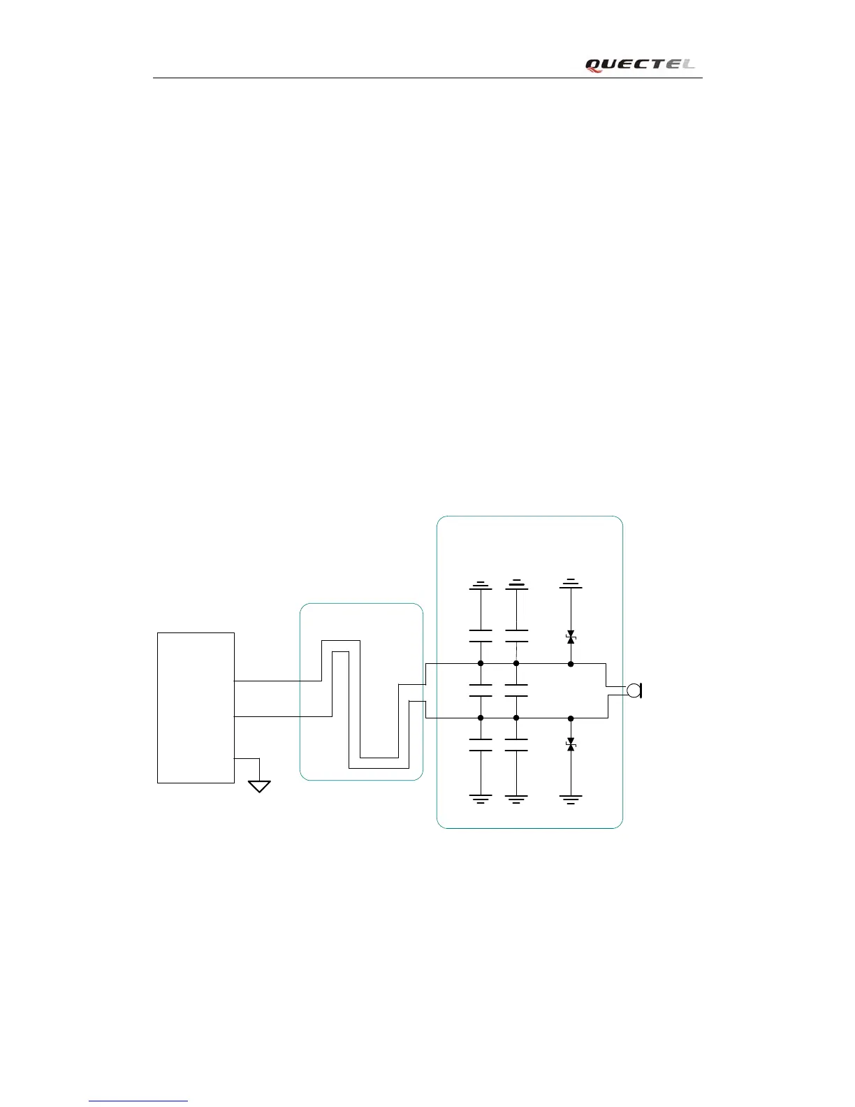
AIN1/IN2 channels come with internal bias supply for external electret microphone. A reference
circuit is shown in Figure27.
10pF
33pF
33pF
33pF
Close to Microphone
MICxP
MICxN
GND
GND
Differential layout
Module
Electret
Microphone
GND
GND
10pF
10pF
GND
GND
ESD
ESD
AGND
Figure 27: Microphone interface configuration of AIN1&AIN2