M10 Hardware Design
M10_HD_V3.0 - 39 -
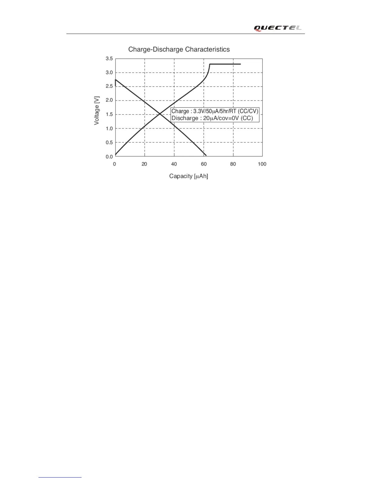
Figure 17: Seiko XH414H-IV01E Charge Characteristic
3.8. Serial interfaces
The module provides two unbalanced asynchronous serial ports including Serial Port, Debug Port.
The module is designed as a DCE (Data Communication Equipment), following the traditional
DCE-DTE (Data Terminal Equipment) connection. Autobauding function supports baud rate from
4800bps to 115200bps.
The UART Port:
TXD: Send data to RXD of DTE
RXD: Receive data from TXD of DTE
RTS: Requests to send
CTS: Clear to send
DTR: DTE is ready and inform DCE (this pin can wake the module up)
RI: Ring indicator (when the call, SMS, data of the module are coming, the module will
output signal to inform DTE)
DCD: Data carrier detection (the validity of this pin demonstrates the communication link is
set up)
Note: The module disables hardware flow control by default. When hardware flow control is
required, RTS and CTS should be connected to the host. AT command “AT+IFC=2,2” is used to
enable hardware flow control. AT command “AT+IFC=0,0” is used to disable the hardware
flow control. For more details, please refer to document [1].