M10 Hardware Design
M10_HD_V3.0 - 54 -
In SIM interface designing, in order to ensure good communication performance with SIM card,
the following design principles should be complied with.
Place the SIM card holder close to module as close as possible. Ensure the trace length of
SIM signals do not exceed 20mm.
Keep the SIM signals far away from VBAT power and RF trace.
The width of SIM_VDD trace is not less than 0.5mm. Place a bypass capacitor close to SIM
card power pin. The value of capacitor is less than 1uF.
To avoid possible cross-talk from the SIM_CLK signal to the SIM_DATA signal be careful
that both lines are not placed closely next to each other. A useful approach is to use GND to
shield the SIM_DATA line from the SIM_CLK line.
In order to ensure good ESD protection, it is recommended to add TVS such as WILL
(http://www.willsemi.com) ESDA6V8AV6. The capacitance of ESD component is less than
50pF. The 22Ω resistors should be added in series between the module and the SIM card so
as to suppress the EMI spurious transmission and enhance the ESD protection. Note that the
SIM peripheral circuit should be close to the SIM card socket.
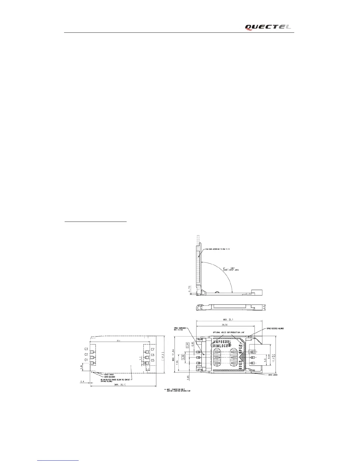
3.10.2. Design considerations for SIM card holder
For 6-pin SIM card holder, it is recommended to use Amphenol C707 10M006 512 2. Please visit
http://www.amphenol.com for more information.
Figure 35: Amphenol C707 10M006 512 2 SIM card holder