Figure 17: Reference Circuit for a 6-Pin (U)SIM Card Connector
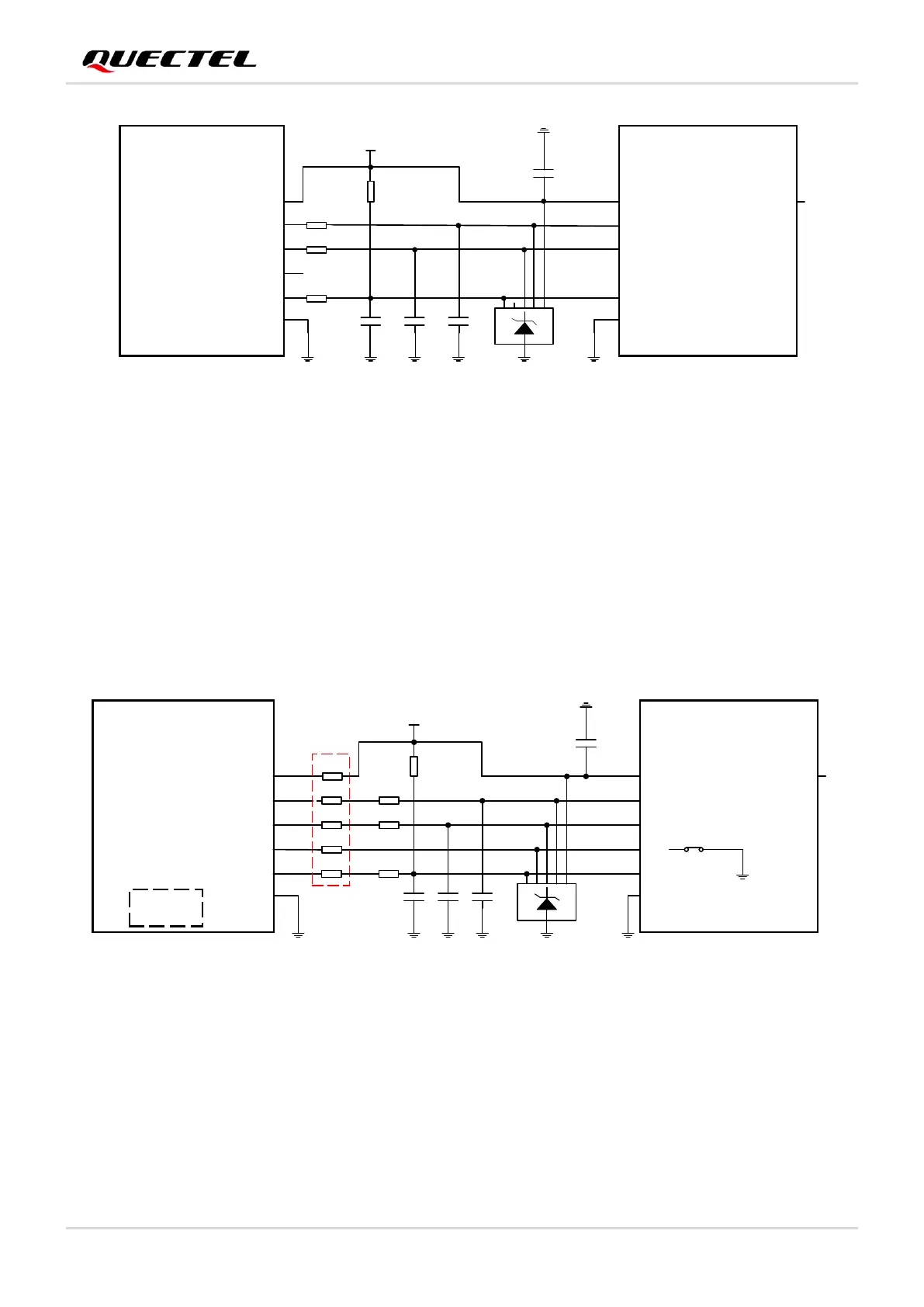
4.1.6. (U)SIM2 Card Compatible Design
It should be noted that when the (U)SIM2 interface is used for an external (U)SIM card, the circuits are the
same as those of (U)SIM1 interface. When the (U)SIM2 interface is used for the optional internal eSIM
card, pins 40, 42, 44, 46 and 48 of the modules must be kept open.
A recommended compatible design for the (U)SIM2 interface is shown below.
M.2 Socket Connector
(U)SIM Card
Connector
USIM2_DET
USIM2_DATA
USIM2_CLK
RST
CLK
CD
IO
USIM2_VDD
USIM2_VDD
USIM2_RST
VCC
GND
VPP
GND
TVS array
NOTE:
The five 0 Ω resistors must be placed close to the module, and all other components should be placed close to
(U)SIM card connector in PCB layout.
48
46
44
40
42
10-20K
22 Ω
22 Ω
22 Ω
10pF10pF 10pF
100 nF
0 Ω
0 Ω
0 Ω
0 Ω
0 Ω
eSIM