20©2006 Sunrise Medical
POWER BASE SECTION
Battery Connectors
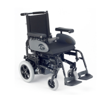
Inspecting the Fuses
Remove caps on each of the two 15 amp fuses and
visually inspect. Insure there are no breaks in the fuse
material. If continuity is still in doubt, unplug fuse from
holder and check resistance across fuse blades. Zero
resistance indicates a usable fuse. Infi nite resistance
indicates a non-usable fuse.
The 100 amp fuse must be checked by measuring their
continuity. Zero resistance indicates a usable fuse.
Infi nite resistance indicates a non-usable fuse. The
100 amp fuse is not replaceable, the harness must be
replaced.
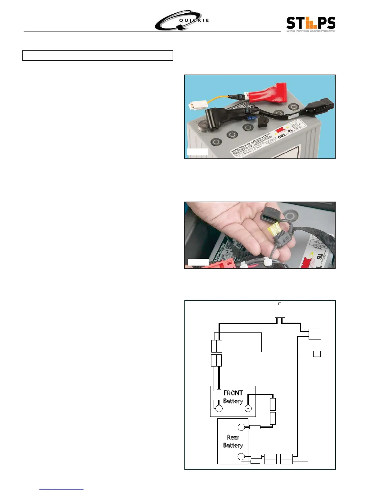
The battery connection uses a 2 way connector with a
White Jumper to give the series connection of 24 volt
It has a clearly designated RED and BLACK connector
which connect to the Positive for RED and the Nega-
tive for the BLACK with JUMPER (White) joining the
system. The system has a 100 amp non-removable
fuse built into the Cable and a removable 15 amp fuse
for Auxiliary Power.
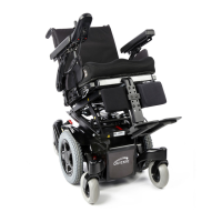
Fuse Wiring Diagram
+
+
+
-
-
+
BLACK
100A
15A
15A
Rear
Battery
100A
YELLOW
YELLOW
FRONT
Battery
100A
RED
RED
RED
RED
RED
BLACK
BLACK
Fig 1.12
Fig 1.11
Fig 1.10