Section III - Installation
CONDENSATE SOLENOID
VALVE
PILOT VALVE
TOWER 2 SOLENOID
PILOT VALVE
AC & DC SUPPLY
DIN CONNECTIONS
ENERGY MANAGEMENT
DIN CONNECTION
CONTROLLER CLEAR
LED COVER
RS232 SOFTWARE
CONNECTION
ALARM DIN
CONNECTION
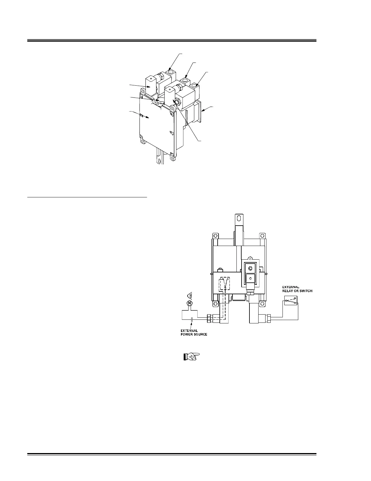
Controller Components
NOTICE!
The user must ensure that the EM DIN
plug as supplied with jumper wire, or
an external switching arrangement
is in place before the dryer becomes
operational.
Ensure the energy management
switching arrangement is in place
before activating the EM facility and
flowing air through the dryer.
Energy Management Connection
Remove DIN plug from EM connection
on controller.
Remove blanking plug from cable entry
nut on DIN plug.
Remove fixing screw and gasket from
DIN plug body.
Separate DIN plug body internal from
cover.
Remove jumper wire from pins 1 and 2
on DIN plug body internal.
Connect external switching device
cable to pins 1 and 2 on DIN plug body
internal, ensuring that cable entry nut,
washer and seal are in place.
Assemble DIN plug body internal into
cover and reconnect DIN plug to EM
connection on controller, ensuring that
screw and gasket are fitted.
The controller gives a +5 VDC from pin
1 on the EM DIN. Operation of the EM
feature is by opening and closing the
circuit.
Opening the circuit with an appropriate
external relay or switch will activate the
EM feature.
•
•
•
•
•
•
•
•
•
12 Quincy Compressor-QMOD